Welcome to the Onshape forum! Ask questions and join in the discussions about everything Onshape.
First time visiting? Here are some places to start:- Looking for a certain topic? Check out the categories filter or use Search (upper right).
- Need support? Ask a question to our Community Support category.
- Please submit support tickets for bugs but you can request improvements in the Product Feedback category.
- Be respectful, on topic and if you see a problem, Flag it.
If you would like to contact our Community Manager personally, feel free to send a private message or an email.
Assemblies and parts
 joseph_newcomer
Member Posts: 101 ✭✭✭
in General
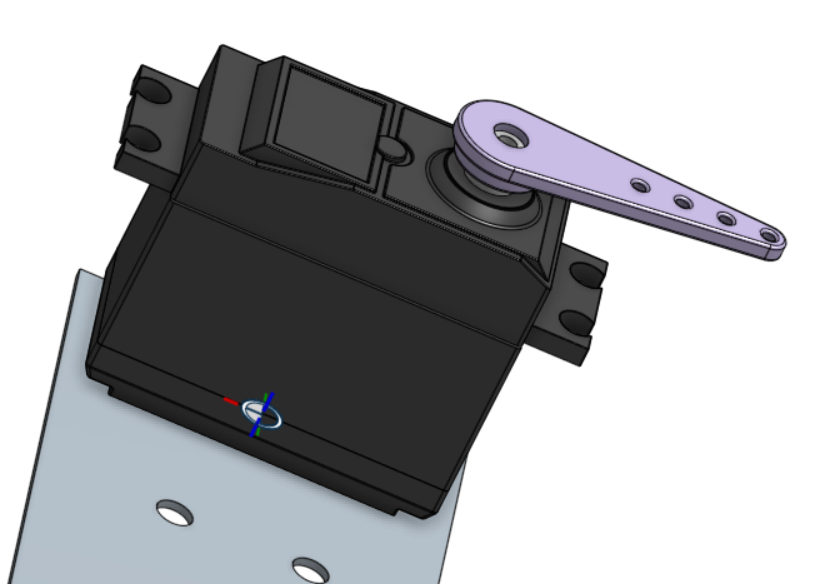
Here is a screenshot of an assembly. The file is
 https://cad.onshape.com/documents/cd1c50678c1b377ca69e7bd7/w/9db17e8af11a8b04576676be/e/cccc756981714a03ed2605a3?renderMode=0&uiState=61d7da80c3cb70796723eeee

The backplate is fixed; the servo is supposed to be able to be moved vertically on it once I get all the necessary dimensions. I'm having some trouble getting the sliding mate to work, but I posted that in an earlier question. So, assuming I get a solution, I now have a servo and a backplate.
This is not really a viable solution; I don't plan to superglue the servo to the backplate. What I really want to do, having gotten this far, is now create a "bracket" to hold the servo motor; imagine a wedge tapering down to zero, and rising to the height of the flanges of the servo. The servo will, essentially "lay on top" of this platform. Then I want to extend the platform up on both sides, and put four holes in so I can bolt the servo to it. The simplest solution would be to create planes very near the sides of the servo and put the sketches on them, do the extrusions and so on. But I'm not sure how to add these ideas to an assembly. I don't want to have to sit here with calipers and create a set of dimensions in a part studio which I then insert into the assembly; I want to use the actual parts. Then, once I get all the dimensions I need (the XY table is not yet assembled), I can adjust distances as appropriate, and then use the holes in the metal plate to place the points for the bolts that will hold the 3D printed "shelf" to the plate, and the servo motor to the "shelf" using those four holds on the servo itself to locate the holes. I keep feeling this should be easier than I am going at it, which means I am probably going at it the wrong way. Even a pointer to the right OnShape lesson would be a great help.
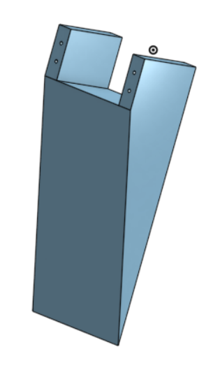
You will find in Part Studio 1 the following model:

This is an almost totally undimensioned representation of what I want to build. What I want to do is make it about .2mm wider than the servo, and the flat part with the holes will come up to the flanges on the servo, and the holes will be centered under the holes in the flanges. This was just a quick & dirty approximation to convey the idea, and no attempt was made to make it elegant or correct as a finished model. The problem is, how to get all the necessary information from the assembly (short of using driven named dimensions, which I think is clumsy).
Thanks in advance
Joe
 https://cad.onshape.com/documents/cd1c50678c1b377ca69e7bd7/w/9db17e8af11a8b04576676be/e/cccc756981714a03ed2605a3?renderMode=0&uiState=61d7da80c3cb70796723eeee
The backplate is fixed; the servo is supposed to be able to be moved vertically on it once I get all the necessary dimensions. I'm having some trouble getting the sliding mate to work, but I posted that in an earlier question. So, assuming I get a solution, I now have a servo and a backplate.
This is not really a viable solution; I don't plan to superglue the servo to the backplate. What I really want to do, having gotten this far, is now create a "bracket" to hold the servo motor; imagine a wedge tapering down to zero, and rising to the height of the flanges of the servo. The servo will, essentially "lay on top" of this platform. Then I want to extend the platform up on both sides, and put four holes in so I can bolt the servo to it. The simplest solution would be to create planes very near the sides of the servo and put the sketches on them, do the extrusions and so on. But I'm not sure how to add these ideas to an assembly. I don't want to have to sit here with calipers and create a set of dimensions in a part studio which I then insert into the assembly; I want to use the actual parts. Then, once I get all the dimensions I need (the XY table is not yet assembled), I can adjust distances as appropriate, and then use the holes in the metal plate to place the points for the bolts that will hold the 3D printed "shelf" to the plate, and the servo motor to the "shelf" using those four holds on the servo itself to locate the holes. I keep feeling this should be easier than I am going at it, which means I am probably going at it the wrong way. Even a pointer to the right OnShape lesson would be a great help.
You will find in Part Studio 1 the following model:

This is an almost totally undimensioned representation of what I want to build. What I want to do is make it about .2mm wider than the servo, and the flat part with the holes will come up to the flanges on the servo, and the holes will be centered under the holes in the flanges. This was just a quick & dirty approximation to convey the idea, and no attempt was made to make it elegant or correct as a finished model. The problem is, how to get all the necessary information from the assembly (short of using driven named dimensions, which I think is clumsy).
Thanks in advance
Joe

0
Comments
Why not use in-context?
https://cad.onshape.com/documents/4f6b5631d2ff4eba91c213b8/w/9d686031d9111758216ae187/e/322b140f4e49bd0638ef7bcb