Welcome to the Onshape forum! Ask questions and join in the discussions about everything Onshape.
First time visiting? Here are some places to start:- Looking for a certain topic? Check out the categories filter or use Search (upper right).
- Need support? Ask a question to our Community Support category.
- Please submit support tickets for bugs but you can request improvements in the Product Feedback category.
- Be respectful, on topic and if you see a problem, Flag it.
If you would like to contact our Community Manager personally, feel free to send a private message or an email.
GT2 Belt
 joseph_newcomer
Member Posts: 101 ✭✭✭
in General
Here is a snapshot of my document, which is shared with this link:

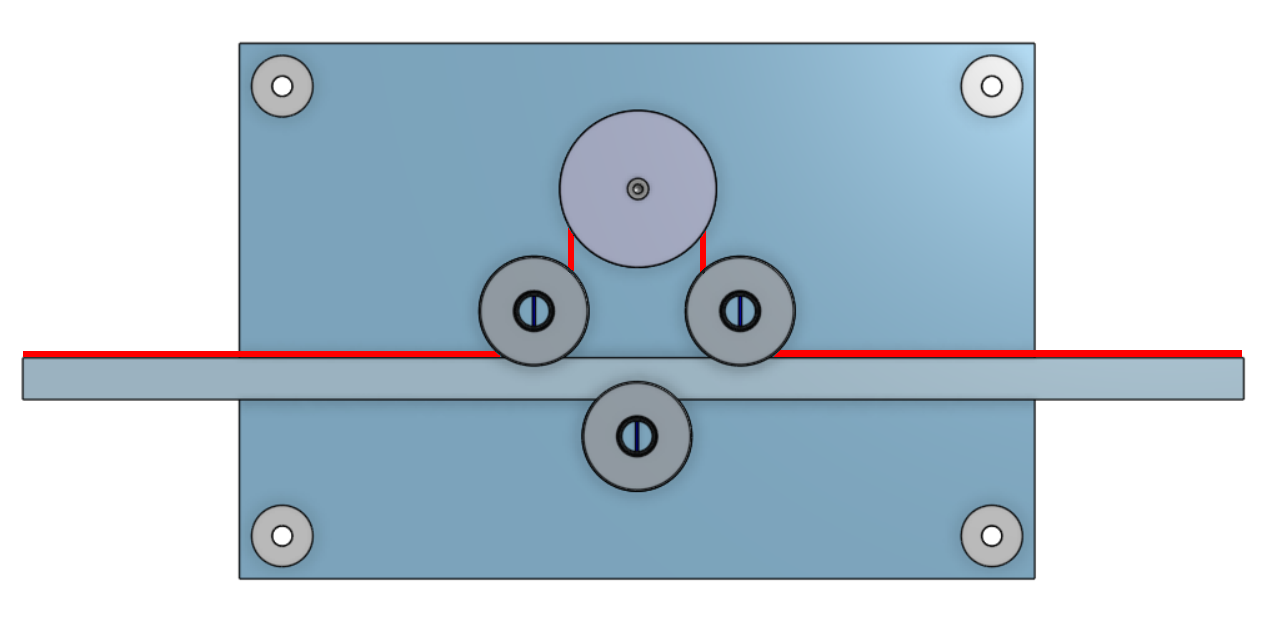
Now, I'm stuck. The red line was hand-drawn in a photo editor from a screen shot of part of the assembly. It represents a GT-2 timing belt. The large circle is a 36-tooth pulley on a servo. All three of the smaller circles represent smooth idler pulleys. Where I'm stuck is figuring out how to get the belt into the drawing so that everything still moves but the belt will also move, and will move the slider back and forth. If there is a tutorial that explains this, I would appreciate a pointer to it.
I have another problem. The slider is held in place by the lower idler, which presses against it. So the obvious thing to do is to make a tangent mate between the bottom face of the slider and the face of the idler pulley. But every time I have tried this, it sets the bottom face of the slider to be tangent to what would be the bottom of the pulley surface, that is, it wants the slider to slide through the middle of the shaft! I have tried several ways to convince it that it should be touching the top surface of the pulley, but thus far I have not been able to convince it this makes sense.
In the assembly of the drawing, the opposite side of this drawing is the "front" of the device. The "back" (which I have made invisible here) is on a slider mate so I can move it up out of the way if I want to add something to the drawing. The four corner circles are spacers that will hold the two major pieces apart. There are also some little extrusions which cause the idlers to come out to the right position to made with the servo gear. They are not yet precise because I am "winging" this since the parts will not be here for another two weeks, so I'm trusting the diagrams associated with the parts, insofar as they can be trusted. All of the idler pulleys are ball-bearing units, so the extrusions hold the center of the bearing in place, and far enough away from the plates that there will be no friction with the outer bearings. There is also a ball bearing on the "back" piece to help reduce some strain on the servo shaft. Right now, for the prototype V1, everything will be 3D printed. Prototype V2 will learn from the mistakes we made here, and probably be machined out of aluminum. The split shafts are to help with the inaccuracies of the 3D printing process; if the shafts are a bit too large, they will compress. Obviously we do not need to worry about this when we have precision shafts cut to length.
0