Welcome to the Onshape forum! Ask questions and join in the discussions about everything Onshape.
First time visiting? Here are some places to start:- Looking for a certain topic? Check out the categories filter or use Search (upper right).
- Need support? Ask a question to our Community Support category.
- Please submit support tickets for bugs but you can request improvements in the Product Feedback category.
- Be respectful, on topic and if you see a problem, Flag it.
If you would like to contact our Community Manager personally, feel free to send a private message or an email.
"Cosmetic Only" overlays (text, graphics) strategy... Using zero offset surface?
 eric_pesty
Member, pcbaevp Posts: 2,640 PRO
eric_pesty
Member, pcbaevp Posts: 2,640 PRO
I have been experimenting with different ways of applying cosmetic graphics to things in Onshape, two common scenarios for us are silkscreen markings on circuit boards as well as road sign version for customer drawings as well as labels.
In SolidWorks we would sometimes get away with an image overlay (for labels) but that's is not an option in Onshape. Using sketches only isn't great as there is usually construction geometry you don't want to see. Surface splits and coloring work but are "expensive" to rebuild and more work to maintain and overkill.
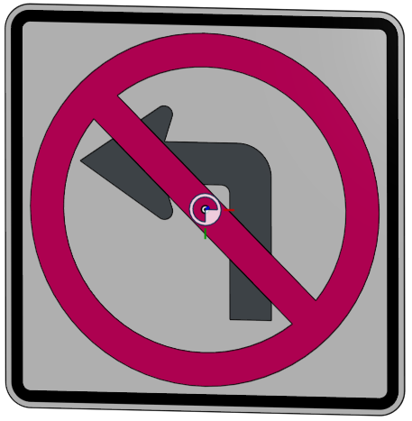
Another option is to crate a separate extruded part. I have been using this for road signs with a boolean to cut away the "background" to avoid any visual artifacts (from the faces of two different solids being coincident) and it works well.
I recently discovered that if you place a surface coincident with a solid face it doesn't produce any artifacts. I guess Onshape is "smart enough" to draw the solid first and the separate surface "over" it. This seems like a good way to do it for circuit boards as all you have to do is crate a "zero offset surface" from the text, create a composite to group all of the faces together and then composite that with the underlying part. this way it doesn't split the face of the PCB and you can also create "blocks" to re-use (by deriving in) in different circuit boards. The only downside is you can't have two surfaces on top of each other or you get visual artifacts.
I'm just wondering if there are any downsides to this I might not be aware of? Anybody doing it this way or found a different "better" way?
Here's an example document showing the different options:
https://cad.onshape.com/documents/8dcf59392e2f2c9b908b7604/w/1f506f3f6a2edd6e6939f68b/e/b903451a95e58a897da4e59d
There is a "blank" background solid part and different configurations for applying the graphics.
The "Solids" option uses parts that are coincident with the background while the "surfaces" are "zero offset" from the front of the background part. I've made the solids black/red and surfaces grey/pink to be able to confirm what I was looking at.
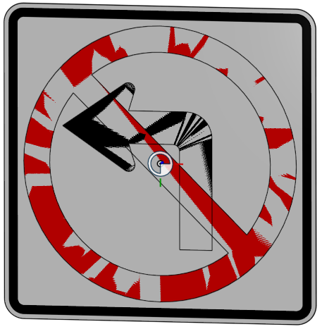
The "no boolean" option shows what happens when the solids aren't cutout from the background or when the surfaces are crossing over each other without trim.
Note that the background is NOT cutout in the surfaces case but I am not seeing any artifacts (except from the back I can see the outline of the surfaces when zooming out/and or not straight on).

In SolidWorks we would sometimes get away with an image overlay (for labels) but that's is not an option in Onshape. Using sketches only isn't great as there is usually construction geometry you don't want to see. Surface splits and coloring work but are "expensive" to rebuild and more work to maintain and overkill.
Another option is to crate a separate extruded part. I have been using this for road signs with a boolean to cut away the "background" to avoid any visual artifacts (from the faces of two different solids being coincident) and it works well.
I recently discovered that if you place a surface coincident with a solid face it doesn't produce any artifacts. I guess Onshape is "smart enough" to draw the solid first and the separate surface "over" it. This seems like a good way to do it for circuit boards as all you have to do is crate a "zero offset surface" from the text, create a composite to group all of the faces together and then composite that with the underlying part. this way it doesn't split the face of the PCB and you can also create "blocks" to re-use (by deriving in) in different circuit boards. The only downside is you can't have two surfaces on top of each other or you get visual artifacts.
I'm just wondering if there are any downsides to this I might not be aware of? Anybody doing it this way or found a different "better" way?
Here's an example document showing the different options:
https://cad.onshape.com/documents/8dcf59392e2f2c9b908b7604/w/1f506f3f6a2edd6e6939f68b/e/b903451a95e58a897da4e59d
There is a "blank" background solid part and different configurations for applying the graphics.
The "Solids" option uses parts that are coincident with the background while the "surfaces" are "zero offset" from the front of the background part. I've made the solids black/red and surfaces grey/pink to be able to confirm what I was looking at.
The "no boolean" option shows what happens when the solids aren't cutout from the background or when the surfaces are crossing over each other without trim.
Note that the background is NOT cutout in the surfaces case but I am not seeing any artifacts (except from the back I can see the outline of the surfaces when zooming out/and or not straight on).

Tagged:
0
Comments
Yes, I am using composites to group things: first closed composite right after the zero offset surface (if you are doing text it creates a ton of them). The apply the color to the faces, and then I do use a composite to group with the underlying part as well.
The sign example above is a bit more tricky of the two colors overlapping each other (which requires trimming the surfaces) but that's not a common issue.
It works reasonably well with larger amounts of text as well, much "lighter" than a split surface for example (the split surface also affect the face of the part itself which can interfere with mating down the road).
In other situations I will have a display state or configuration which has traffic light colors for where paint needs to be (green), where overspray is OK (yellow), and where it must be masked so there's no paint (red). This seems to work with many vendors, and is much easier than hatching faces in 2D views, or arrows pointing to surfaces.
If you are rendering the 3D model, the answers to this question may be very different depending on the tools you're using.
Simon Gatrall | Product Development, Engineering, Design, Onshape | Ex- IDEO, PCH, Unagi, Carbon | LinkedIn
I don't know what this would look like when imported in another software (for rendering or whatever) so that is why I sticking with the "solids" approach for the signs as these are quite likely to be exported. Also the renderstudio seems to struggle with these zero offset faces...
https://cad.onshape.com/documents/1627ceeb06d2c8c166d09506/w/782fec3420d376c36d773949/e/d211a6ebb091ca022e2171b6?renderMode=0&uiState=61fcf28b00e96f71031b9780
Eduardo Magdalena C2i Change 2 improve ☑ ¿Por qué no organizamos una reunión online?
Partner de PTC - Onshape Averigua a quién conocemos en común
Thanks, I was using split faces at some point but in the more complicated cases with more configurations it took quite a bit of work to get the selection sets correct with various configurations (especially when the underlying faces change with different configurations).
Using solid bodies was simpler in the end as you can just set the selection for a composite parts or boolean to include "all possible bodies" and it still rebuilds fine if you suppress some of them through configurations (and use "all bodies" for the scope for example)
What is the problem with configurations and use split face?
You can configure the split face feature too, and even you can configure the selection of the split feature, as you can see
I just found a minor issue. Sometimes it can't solve properly the configuration change.
But if you edit the feature (without change anything) it works fine
Eduardo Magdalena C2i Change 2 improve ☑ ¿Por qué no organizamos una reunión online?
Partner de PTC - Onshape Averigua a quién conocemos en común
We have been using solids this way as it gives a very reliable and flexible result so it is worth it for us to have a few more features.
What I was most curious about was if anyone was using the "zero offset face" as I sort of discovered by accident that it was an option as I didn't think it would display properly. It offers better performance than a split face is reasonably easy to work with.
I was also wondering what other options people were using that I might not have tried!