Welcome to the Onshape forum! Ask questions and join in the discussions about everything Onshape.
First time visiting? Here are some places to start:- Looking for a certain topic? Check out the categories filter or use Search (upper right).
- Need support? Ask a question to our Community Support category.
- Please submit support tickets for bugs but you can request improvements in the Product Feedback category.
- Be respectful, on topic and if you see a problem, Flag it.
If you would like to contact our Community Manager personally, feel free to send a private message or an email.
Cannot 'wake up' points of a face I'm trying to Sketch on.
 daniel_moore
Member Posts: 4 ✭
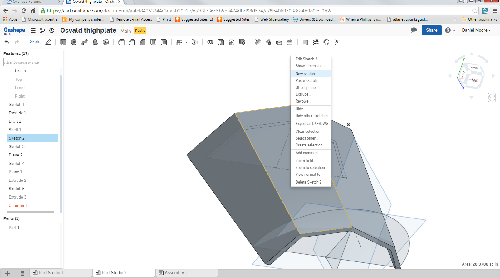
So I've made a surface, and now want to raise features off of that surface.

I start, naturally, by selecting the surface, and select New Sketch.
Once I've done that, I can easily 'wake up' points on the surface.

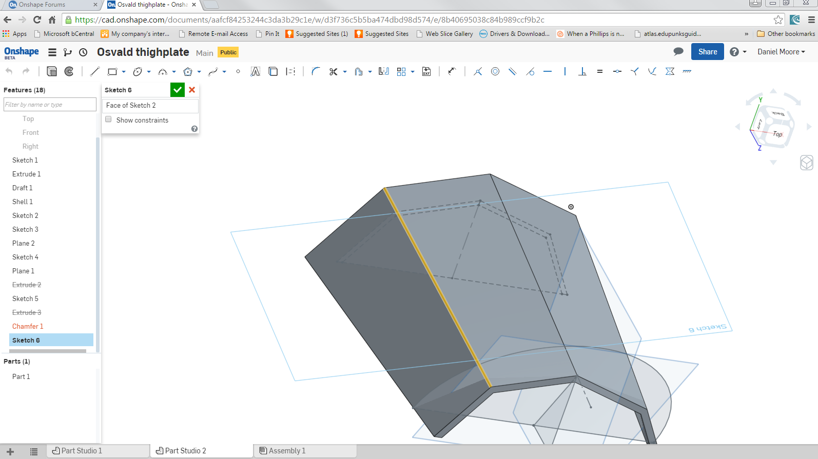
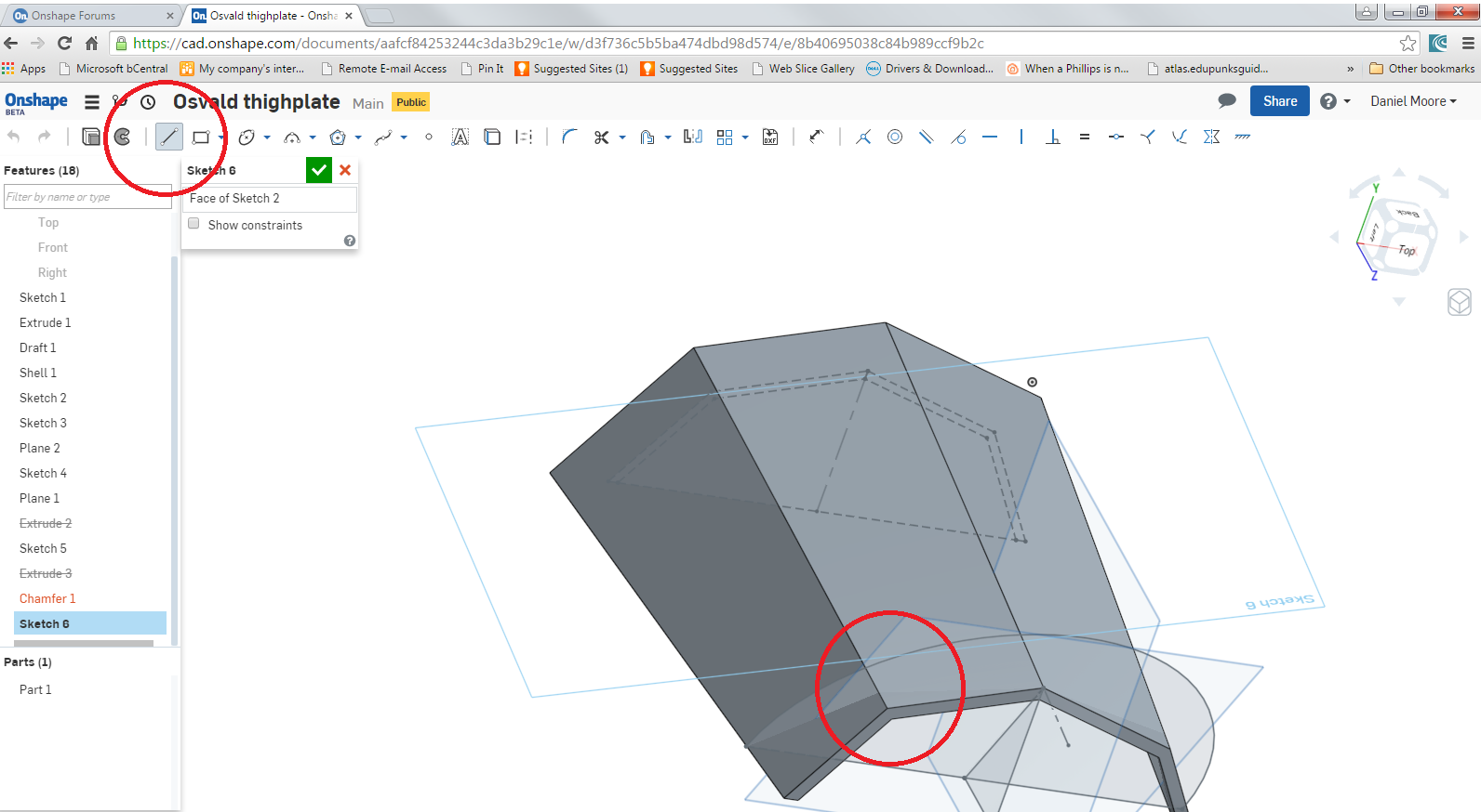
But the moment I actually select the Line Tool, suddenly the points and lines I want to 'draw over' are cold and dead.

What is going on?
Also, Kudos to whomever looks at the filename and figures out what a madman I am. I've a novice at this, and this part is probably quite beyond my skills.
Cheers!

I start, naturally, by selecting the surface, and select New Sketch.
Once I've done that, I can easily 'wake up' points on the surface.

But the moment I actually select the Line Tool, suddenly the points and lines I want to 'draw over' are cold and dead.

What is going on?
Also, Kudos to whomever looks at the filename and figures out what a madman I am. I've a novice at this, and this part is probably quite beyond my skills.
Cheers!
0
Comments
You should be able to work around this limitation (which I think is due to the points you are trying to infer to not lying on the same plane as the sketch)
by
a) instead putting your linework down, then picking an endpoint of that linework, and a point you are trying to infer to, and creating a "Coincident" constraint (which constrains the former to the PROJECTION onto the sketch plane of the latter)
b) selecting a line on the remote sketch and the "Use/Project" tool to bring it through into the active sketch.
I have an immense amount to learn about mirroring in more than one plane, and need to learn how to make there not be gaps between the features raised on two adjacent surfaces, but this was a big help.
I'm also learning a great deal about how the order of events matters in a huge way.
See how those raised features merge into the disk-portion? That only happens if I Extrude and Chamfer the disk *after* raising the features, otherwise there's a very unsightly gap.
If I wanted those inner diamonds to cut in the disk, what would you recommend? Project the diamond drawing up, then Extrude >> Remove downward?
OK, I found your document in the Public folder, and made a few tentative changes, here, in the third tab:
https://cad.onshape.com/documents/74dd733580be4eb4a71ce10d/w/f6b0ceb02d0540798bbae6f8/e/13b56f6a97514e31a0e5de12
The second tab is a snapshot of the state of the model when I copied it
Tentative suggestions include:
1) Made Sketch 1 trimmed geometry, fully defined, and symmetrical to Right construction plane (if I infer your intentions correctly)
2) Cut solid body in half immediately after drafting. This halves the user workload from then on
3) It was then necessary to select the (new) inside face of the halved solid, so it would shell properly
4) Sketch 2 and 3 and Plane 2 are no longer needed because the Right construction plane now acts as the symmetry plane
5) Sketch 4 needs to be reparented to Right Plane (and apex of triangle constrained to vertical edge, so it goes black)
6) Relocated Extrude 3 earlier up the tree, used draft instead of chamfer, made new body, split in half, combined with existing part, and removed unwanted faces using Delete Face in two places (had to fudge draft angle slightly from 60deg to 58 to achieve clean geometry)
7) Mirrored the resulting body
8) Used Delete Face again to clean up the inside (2 faces selected)
These last two steps should remain at the bottom of the tree. You can carry on where I left off by dragging the roll bar up above the mirror feature.
This should give you a cleaner basis to proceed. If you inspect the part by moving the "Rollback" bar you can try to make sense of my changes.
I didn't venture further because I was not clear just what end result you intend, but if you have a crack at taking it further I will be happy to try to help again.
Trimmed geometry means that the endpoints of adjacent entities are constrained to be coincident. I don't know how you are currently creating linework, but it does not generally result in trimmed geometry, so it is very difficult to modify (when you drag one of your sketches, many junctions become detatched). It might simply be that you are not pausing long enough when starting a new line at the endpoint of an existing entity to allow the coincident constraint icon time to flash up.
Have a look at the tutorials on basic sketching and see if you can find a method of creating linework which suits your mindset. To trim existing linework which has not been created using an "approved method" (or which has been imported from a dxf), the only way I know is to extend each entity past the intersection using "Extend", then use the scissor icon under the same pulldown menu to trim off the surplus bits.
If a part is symmetrical (or substantially so) it is never a bad idea to model only half of it. Or, if there are two planes of symmetry, a quarter of it.
Even if there are superficial asymmetrical elements which can be added after the mirror operations, it is beneficial to use symmetry not just to reduce workload, but to ensure the final result remains symmetrical even when edited.
Perhaps the next most important point is this: try not to leave sketches under-defined (blue lines). It leaves the model vulnerable to unintended changes and can make future edits extremely problematic. This is why I added a bunch of dimensions to some of your sketches.
Redefining your sketch 6 was what took the majority of the time in my changes to your model: I had to do this before I could reposition it (because the underlying model had changed) without it turning into a monkey-puzzle tree.
And thirdly: try not to "hang" features off existing geometry such as faces or edges if there is any alternative. It's much more robust if you use construction planes rather than faces or sketch planes wherever possible, and somewhat more robust if you reference sketch geometry rather than model edges.
I immensely appreciate all your help.