Welcome to the Onshape forum! Ask questions and join in the discussions about everything Onshape.
First time visiting? Here are some places to start:- Looking for a certain topic? Check out the categories filter or use Search (upper right).
- Need support? Ask a question to our Community Support category.
- Please submit support tickets for bugs but you can request improvements in the Product Feedback category.
- Be respectful, on topic and if you see a problem, Flag it.
If you would like to contact our Community Manager personally, feel free to send a private message or an email.
How to create an angle constrain with respect to faces - irrespective of any point?
 Jeffrey_5
Member Posts: 5 ✭
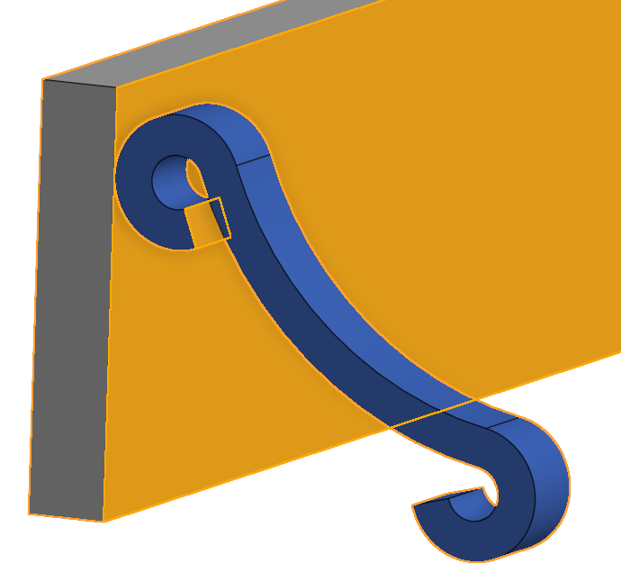
Trying to define an angle between the two highlighted faces and I'm not sure how. The top semi circle of the blue part is tangent to the vertical grey face, and the bottom semi circle is tangent to the bottom face.
Only ways I've seen that are close are using something like either a fasten or planer mate with an angle rotation. I'm not sure what to select with this though because any geometry I select on the grey part defines the angle plane to be coincident with the point. With the geometry as is, I could define a planar mate with an angle through the arbitrary/imaginary intersection of the two planes. That seems as though it would take extra calculation/math/geometry in some way, so doesn't feel like a reasonable method.
I've worked around this by defining where the center of one of the circles. Between that, the tangents and a mate to make the parts flush it's fully constrained. But that also requires me already knowing the center location with respect to geometry.
So, any thoughts or methods that I'm missing?

0
Best Answer
-
 S1mon
Member Posts: 3,768 PRO
@Jeffrey_5
Sorry that wasn't more clear. It may be a lot easier to add the needed mate connector in the part studio instead of trying to completely manage the mates in the assembly.Simon Gatrall | Product Development Specialist | Open For Work
2
Answers
Simon Gatrall | Product Development Specialist | Open For Work
So does that mean doing as you say I'd have to 1. Add the sketch geometry 2. Insert the sketch 3. Constrain sketch to 3D geometry 4.Create mate connector based on sketch and then 5. Create the mating connection ?
Is that right or am I missing something. Please let me know if this is what you were thinking or let me know what I'm missing/point me to some instruction.
Sorry that wasn't more clear. It may be a lot easier to add the needed mate connector in the part studio instead of trying to completely manage the mates in the assembly.
Simon Gatrall | Product Development Specialist | Open For Work