Welcome to the Onshape forum! Ask questions and join in the discussions about everything Onshape.
First time visiting? Here are some places to start:- Looking for a certain topic? Check out the categories filter or use Search (upper right).
- Need support? Ask a question to our Community Support category.
- Please submit support tickets for bugs but you can request improvements in the Product Feedback category.
- Be respectful, on topic and if you see a problem, Flag it.
If you would like to contact our Community Manager personally, feel free to send a private message or an email.
Formed features in Sheet Metal environment
 bryan_lagrange
Member, User Group Leader Posts: 950 ✭✭✭✭✭
in General
Working in a sheet metal job shop we sometimes have formed features such as louvers that are placed on sheet metal parts that we manufacture.
When manufacturing sheet metal parts it is good to know how these features are added in the manufacturing process and what is needed from the CAD side to produce this.
The most common formed feature we apply are louvers, so I will use this as an example.
To create a sheet metal part with louvers we use a CNC laser to cut the part and a CNC press brake to put the louver in the cut part (along with making bends). For the laser on the CAM side I need to have a line in the .dxf that will be used to make a kerf width cut to place the louver. The cut relieves the open area that the louver will make in the metal. When forming it I need to show location of the louver and type for the press brake operator (we have 2 sizes 5in and 9in long louver).
Here is how I accomplish it in Onshape (I will use my public account so everyone can have access to the Onshape document https://cad.onshape.com/documents/e527e3d9c840215a5e5ebef3/w/993910e9201c1d24fa058359/e/a0c7643ecc54f55ca7307515 ) :
First I created a library with the 5in and 9in long louver. I made just a surface of this feature so that when I add it to my sheet metal part, as a derived component, I can combine the surface and the part using the thickening command entering the thickness of the sheet metal part:
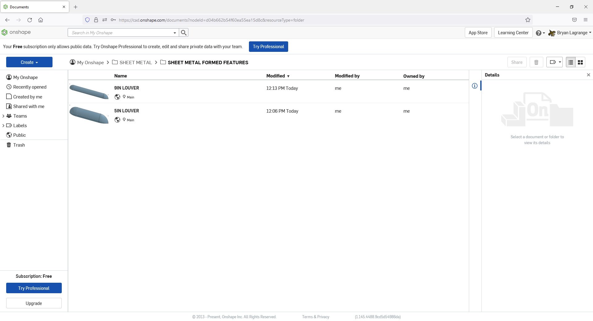
5in louver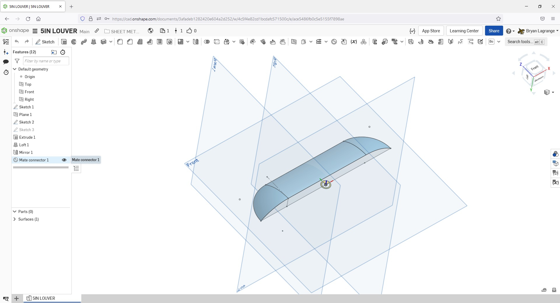
I create my sheet metal part with all the features that will be needed to laser cut. For the louvers, I place a line then use the symmetrical offset with a.001" diameter. I will use this to make a cut into the sheet metal. The CAM software we use will recognize a .001" diameter slot as a single line, which is what we need to make the kerf width cut for the louver.
I create a sketch of the cut, Remove extrude the sketch, pattern the remove extrude. I also place a mate connector where I want to place the derived formed feature on the part.
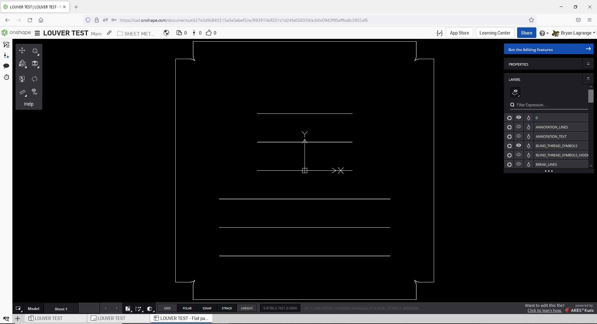
Since these are all the features I need to laser cut this part, I will finish the sheet metal part and get the flat pattern I need to create a .dxf (programmed in CAM) for laser cutting.
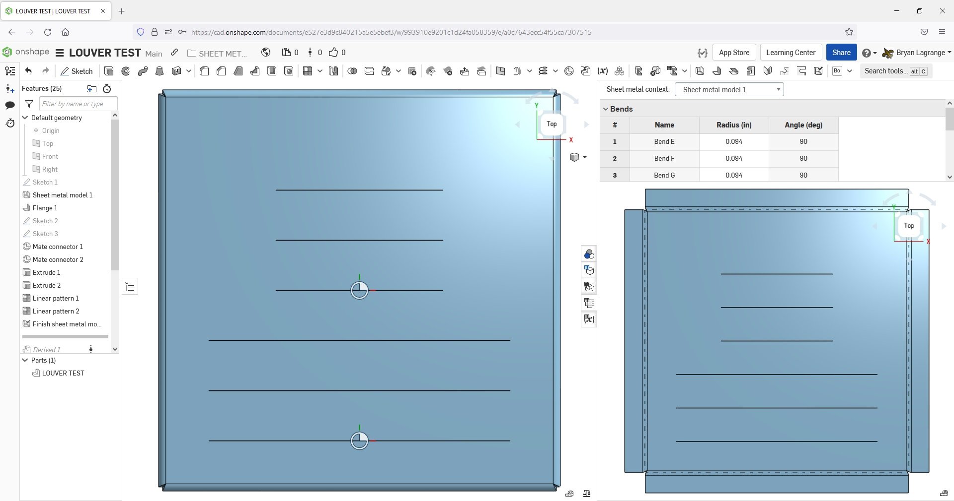
DXF of sheet metal part.
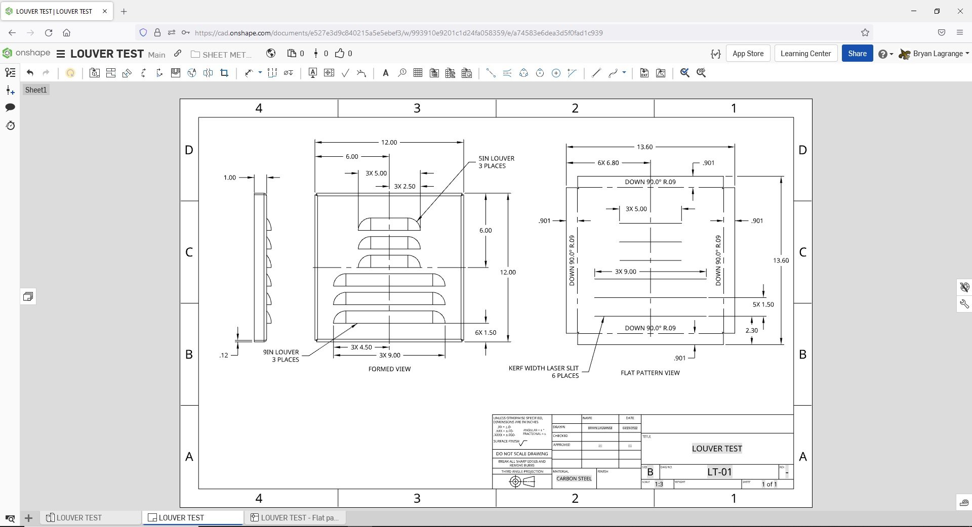
Now to depict the louvers onto the part. The depiction of the louvers in the manufacturing drawing is need for the press brake operator to place them and for final QC inspection:
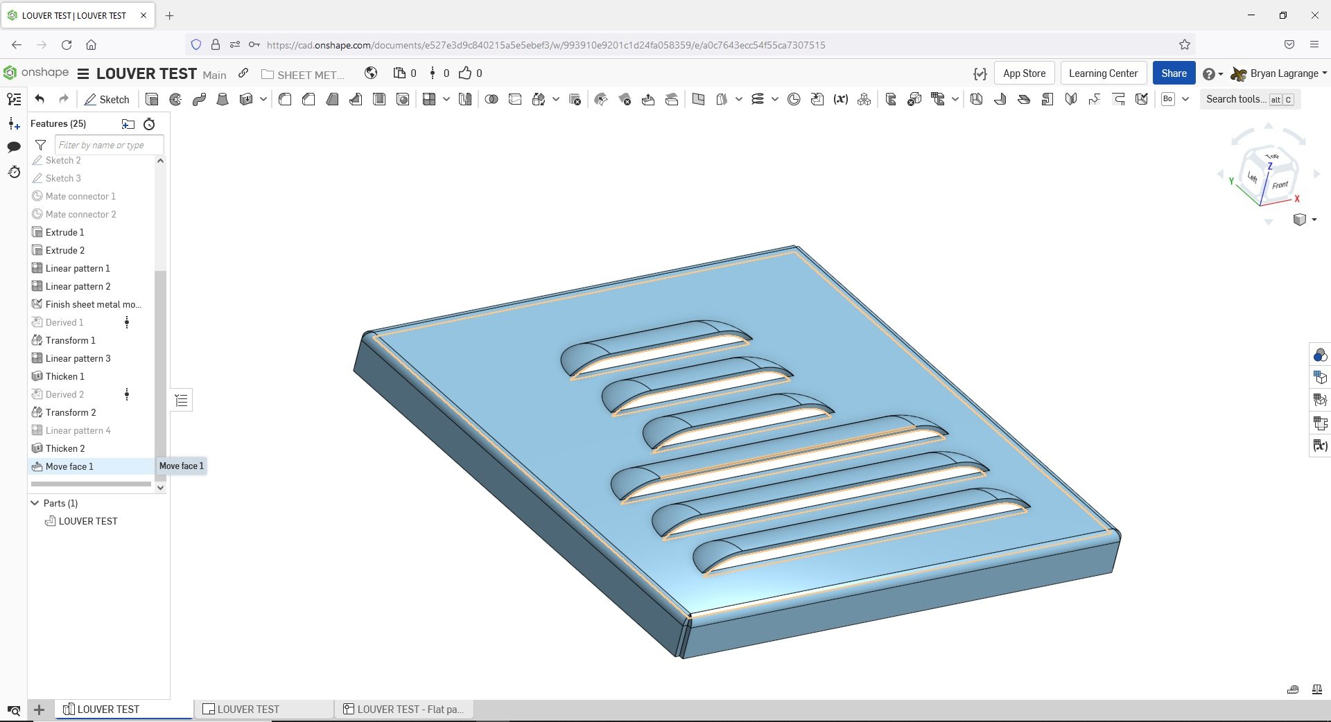
I will use the derived function and go to my sheet metal formed feature library and select the louver I want.
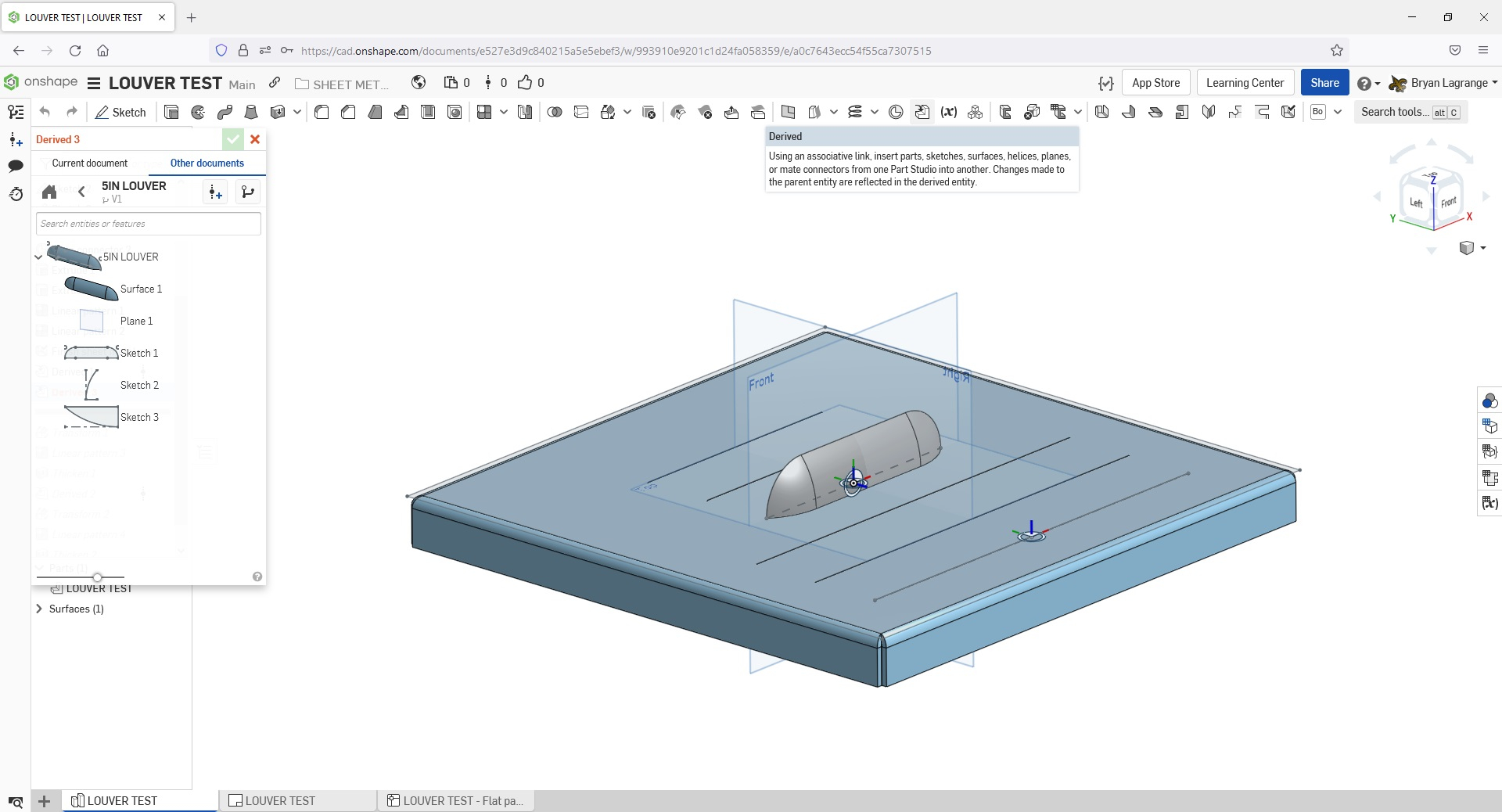
I will use the transform command to place the feature via the mate connector.
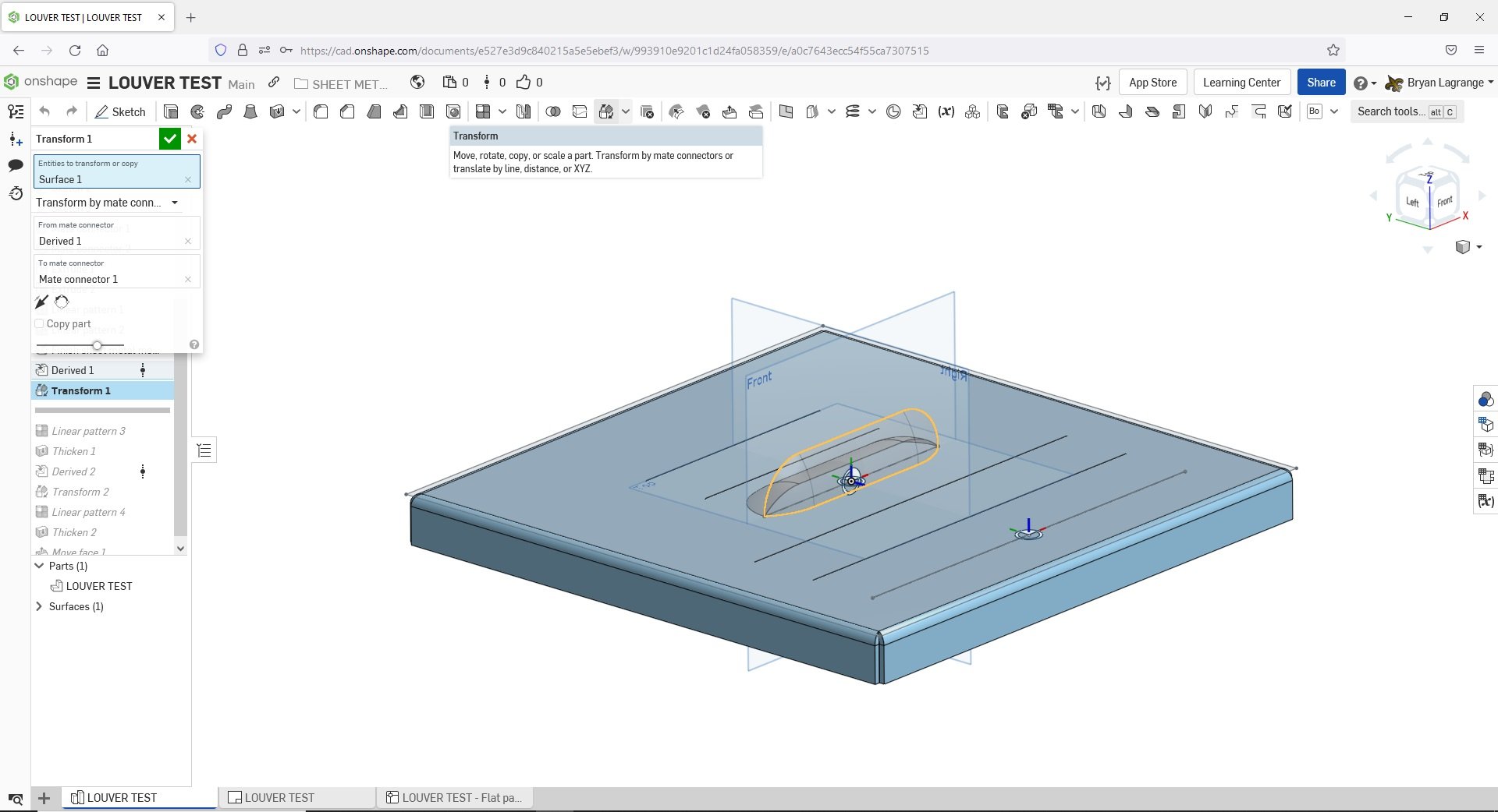
I will then pattern the surface to the amount of louvers I need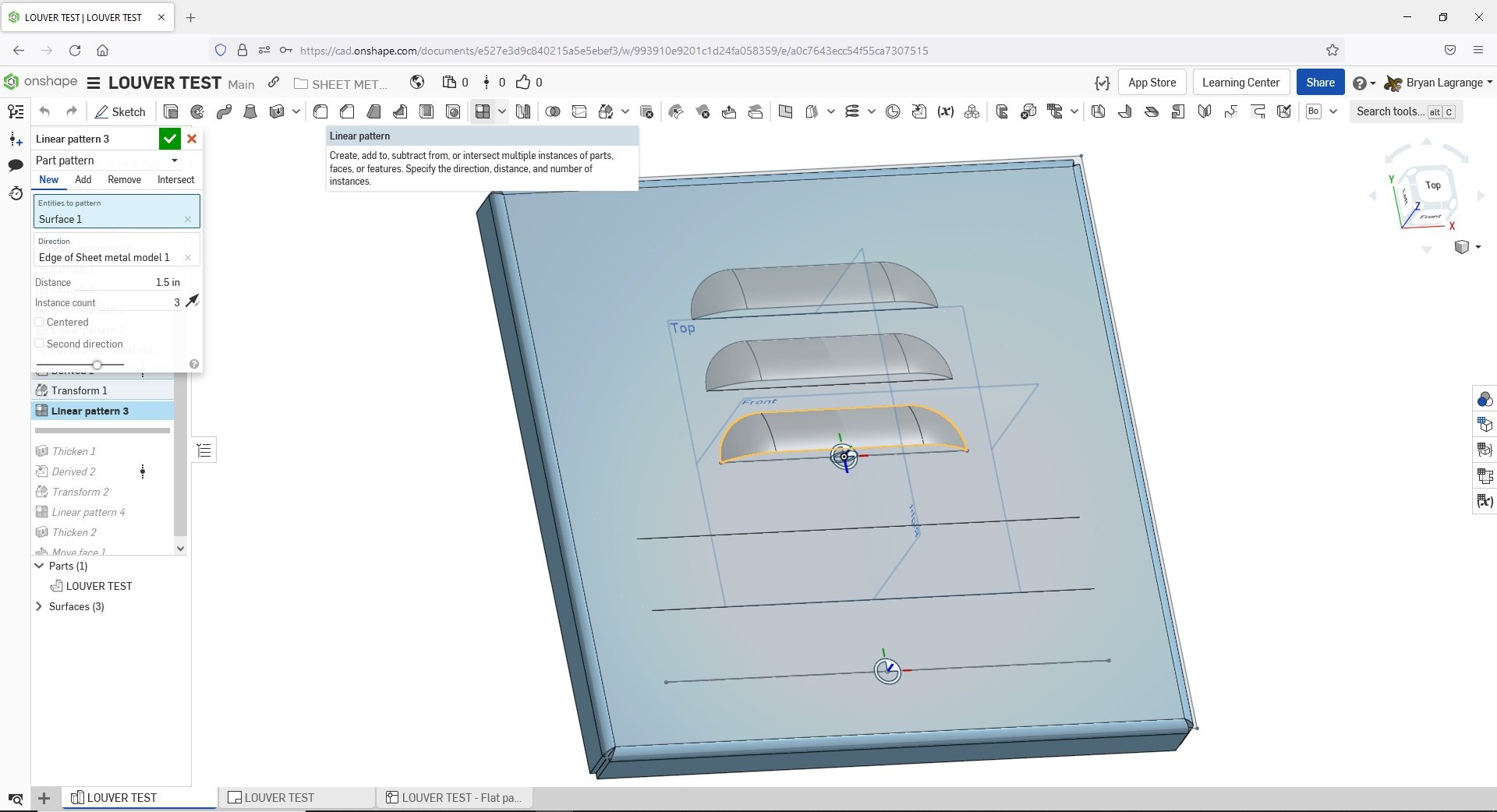
I will Thicken and use the Add option to add the feature to the sheet metal part. In the thicken command I will enter the thickness of the sheet metal part.
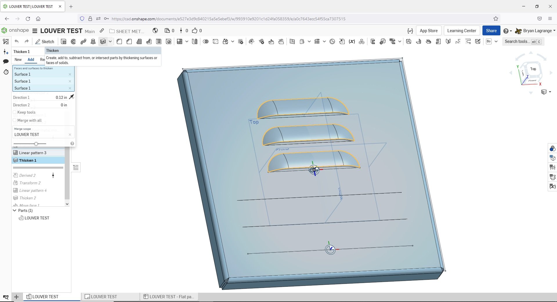
For a final look I find using the move face feature helpful. I simply select the faces in the louver area that needs to be removed and move them to create a louver opening. This is an optional step if you want to complete the look. You could also use the extrude remove option.
Here is the resulting manufacturing drawing that both the press brake operator and laser operator (along with the .dxf file for CAM purposes) would use to create the part.
When manufacturing sheet metal parts it is good to know how these features are added in the manufacturing process and what is needed from the CAD side to produce this.
The most common formed feature we apply are louvers, so I will use this as an example.
To create a sheet metal part with louvers we use a CNC laser to cut the part and a CNC press brake to put the louver in the cut part (along with making bends). For the laser on the CAM side I need to have a line in the .dxf that will be used to make a kerf width cut to place the louver. The cut relieves the open area that the louver will make in the metal. When forming it I need to show location of the louver and type for the press brake operator (we have 2 sizes 5in and 9in long louver).
Here is how I accomplish it in Onshape (I will use my public account so everyone can have access to the Onshape document https://cad.onshape.com/documents/e527e3d9c840215a5e5ebef3/w/993910e9201c1d24fa058359/e/a0c7643ecc54f55ca7307515 ) :
First I created a library with the 5in and 9in long louver. I made just a surface of this feature so that when I add it to my sheet metal part, as a derived component, I can combine the surface and the part using the thickening command entering the thickness of the sheet metal part:

5in louver

I create my sheet metal part with all the features that will be needed to laser cut. For the louvers, I place a line then use the symmetrical offset with a.001" diameter. I will use this to make a cut into the sheet metal. The CAM software we use will recognize a .001" diameter slot as a single line, which is what we need to make the kerf width cut for the louver.
I create a sketch of the cut, Remove extrude the sketch, pattern the remove extrude. I also place a mate connector where I want to place the derived formed feature on the part.
Since these are all the features I need to laser cut this part, I will finish the sheet metal part and get the flat pattern I need to create a .dxf (programmed in CAM) for laser cutting.

DXF of sheet metal part.

Now to depict the louvers onto the part. The depiction of the louvers in the manufacturing drawing is need for the press brake operator to place them and for final QC inspection:
I will use the derived function and go to my sheet metal formed feature library and select the louver I want.

I will use the transform command to place the feature via the mate connector.

I will then pattern the surface to the amount of louvers I need

I will Thicken and use the Add option to add the feature to the sheet metal part. In the thicken command I will enter the thickness of the sheet metal part.

For a final look I find using the move face feature helpful. I simply select the faces in the louver area that needs to be removed and move them to create a louver opening. This is an optional step if you want to complete the look. You could also use the extrude remove option.

Here is the resulting manufacturing drawing that both the press brake operator and laser operator (along with the .dxf file for CAM purposes) would use to create the part.

4
Comments
We also use a single louver body with configurations for the different sizes we use instead of using separate ones, which makes it very easy to change to a different size louver if needed.
Learn more about the Gospel of Christ ( Here )
CADSharp - We make custom features and integrated Onshape apps! Learn How to FeatureScript Here 🔴
Twitter: @BryanLAGdesign
Twitter: @BryanLAGdesign
Twitter: @BryanLAGdesign
Learn more about the Gospel of Christ ( Here )
CADSharp - We make custom features and integrated Onshape apps! Learn How to FeatureScript Here 🔴
Formed features on sheet metal parts are probably more efficiently made using a CNC turret punch. On these machines you can do a variety of formed features such as single hit louvers, progressive louvers, dimples, specialty stamps, and host of other variety features. Depending on the CAM software, some would just need a start and stop point or a center point like a cross hair on the flat pattern to indicate where to place the formed feature.
Twitter: @BryanLAGdesign
The Onsherpa | Reach peak Onshape productivity
www.theonsherpa.com
Fs: https://cad.onshape.com/documents/a752e0db24eb071ebb6f5aa0/v/b183b414b4b032149272ccee/e/e5c2abf7dd42d71d28468eca
Example: https://cad.onshape.com/documents/a10a02b6cd4e0f7135ebd75a/w/1eea426fd389eef3dff978e9/e/efac18eae0173ec1830b587b?renderMode=0&rightPanel=sheetMetalPanel&uiState=628c743009d1b23dcdd13f31
Learn more about the Gospel of Christ ( Here )
CADSharp - We make custom features and integrated Onshape apps! Learn How to FeatureScript Here 🔴