Welcome to the Onshape forum! Ask questions and join in the discussions about everything Onshape.
First time visiting? Here are some places to start:- Looking for a certain topic? Check out the categories filter or use Search (upper right).
- Need support? Ask a question to our Community Support category.
- Please submit support tickets for bugs but you can request improvements in the Product Feedback category.
- Be respectful, on topic and if you see a problem, Flag it.
If you would like to contact our Community Manager personally, feel free to send a private message or an email.
Timing Belt Pulley (New FeatureScript)
 maximilian_schommer_trilobio
Member Posts: 7 PRO
maximilian_schommer_trilobio
Member Posts: 7 PRO
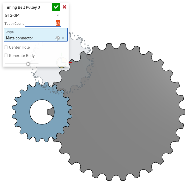
TLDR: Featurescript to create timing belt pulleys. Currently supports GT2-2M and GT2-3M profiles. I'd appreciate feedback on which other profiles to support next.


Then I begin mathematically defining constraints as a system of equations.
At the end of the day, the pulley profile was barely solvable. I was trying to create a closed-form solution for the center distance of two pulleys given the belt length and two pulley radii, and was defeated by a (likely) unsolvable system.
This feature was created by analytically solving for points for the timing belt profile using Sympy. An iPython notebook giving more details about this process is located here:
Additional tooth profiles can be supported if the profiles are solved for. Feel free to create a PR with additional solutions if you'd like to get a profile added, or post a comment here about a profile you would like supported.
P.S.
This feature was quite the slough. Maybe it didn't need to be this difficult, but I'd love for some feedback on how to do this better. You might think that a timing belt featurescript should be around as easy as a spur gear one, except that all of the formulas for spur gears have been calculated centuries ago, and timing belt profiles are defined by modern CAD systems as sketches. Going from a drawing to a mathematically defined entity without using skConstraint (since I'd like the solution to not be dependent on initial conditions) proved to be very complex, even for a simple drawing. I'll walk through briefly how I solved for the
Here's the specification for the GT2-2M and GT2-3M belt profiles I found.
First, I convert the drawing from cartesian to polar, and define a set of variables which need to be solved.
Then I begin mathematically defining constraints as a system of equations.
Is there a better way to do this kind of drawing-defined feature in Featurescript, without having to try to analytically solve for the points? I know that I *could* use skConstraint, but I then need to guess at a good set of initial conditions to make sure the sketch doesn't become wonky at some set of parameters. I could also make a configurable part studio with a sketch inside it defining one tooth, but then how do I associate each variable with the points in the sketch?
Hopefully this can at least be guidance/a warning for others thinking of attempting the analytical solutions route.
Cheers,
Max
6
Comments
Wanted to drop a few suggestions (just thinking out loud) on some of the things you mentioned.
It seems like a lot of effort deriving analytical solutions to different belt geometries - perhaps it would be easier to create a configurable part studio, and then import into FeatureScript if desired. But if you enjoy it, then go for it!
"I could also make a configurable part studio with a sketch inside it defining one tooth, but then how do I associate each variable with the points in the sketch?"
- If you are referring to the radii and lengths that define the belt tooth profile (in the table you provided), then perhaps you could use a List Configuration Variable to set those. I've provided an example here if interested.
"I'd like the solution to not be dependent on initial conditions... I know that I *could* use skConstraint, but I then need to guess at a good set of initial conditions to make sure the sketch doesn't become wonky at some set of parameters."
- Perhaps your 'initial values' that you assign to the sketch geometry before applying constraints could be one of the belt profiles in your table - they already serve as a solution to the constraints, so there shouldn't be any unexpected behavior as constraints are applied.
"I was trying to create a closed-form solution for the center distance of two pulleys given the belt length and two pulley radii"
- I may have made a mistake in my algebra, but the expressions I'm getting are:
φ + cot(φ) = (L - π(R1 + R2)) / (2 * (R2 - R1)),
d = (R2 - R1) / sin(φ).
for belt-pulley angle φ, pulley radii R1, R2, total belt length L, center-center distance d, and R2 >= R1.
I think you are correct - there probably is no explicit expression for φ and d. You can find φ numerically (φ + cot(φ) is monotonically decreasing).
Hopefully some ideas to explore!
- How can you solve for the center-to-center distance? I get that it's possible to make the diagram, but the actual solution I think may not be possible.
" Could you clarify what you mean by 'initial conditions' - I usually see this term in the context of kinematics/dynamics problems?"
- Sketches are "solved" by taking a set of initial conditions (the initial locations that the user draws the objects in), and then using an iterative optimizer to move all of the sketch bodies until the constraints given by the user converge. This is why sometimes when regenerating a sketch, if a variable is changed, the result can become very messed up from it's original design. It's because a different solution was converged to by the optimizer. The initial conditions (initial locations of the sketch entities) are what determine what solution is chosen. One advantage of an analytical solution is that this is guaranteed not to happen, since the particular solution is chosen explicitly.
https://cad.onshape.com/documents/9cffa92db8b62219498f89af/w/06b332ccabc9d2e0aa0abf88/e/99672d1e329b38e647d90146
As a side note, looking at the performance analysis for your FeatureScript, it seems like you might be able to speed things up pretty dramatically by combining your extrudes into a single operation:
opExtrude(context, id + "extrude", {<br>"entities" : ...,<br>"direction" : ...,<br>"endBound" : BoundingType.BLIND,<br>"endDepth" : (isSymmetric) ? extrudeDist / 2 : extrudeDist,<br>"startBound" : BoundingType.BLIND,<br>"startDepth" : (isSymmetric) ? extrudeDist / 2 : undefined<br>});<br>I'm definitely interested to see how your work progresses, particularly if you're able to make any headway in regards to supporting belts with multiple pulleys/idlers. Very impressive work so far!FRC Design Mentor - Team 1306 BadgerBots
Ah, gotcha. Thanks!
"How can you solve for the center-to-center distance? I get that it's possible to make the diagram, but the actual solution I think may not be possible."
I think you're right - a closed-form analytical solution is probably not possible. Alex Kempen provided a link to an approximate solution which may be sufficient for your needs. Or it could serve as a great place to begin your search algorithm if you want to go the numerical route.
The function in question is f(x) = x + cot(x) - a, and we just want to find the root. cot(x) diverges at 0 and PI, and is monotonically decreasing, so we know one and only one root exists on that interval. [Graph here]. You could use, for example, a bisection search to get as close as you like to the solution. That's the method I'm most familiar with - I use it for f(x) = x + tan(x) - a in a gear script.
Just throwing out ideas for you to play with - keep up the great work!
perfect work, thanks a lot!
I often a htd 8m pulley I would love to be able to generate this
I was just asked if I could make a model of a custom T2,5 timing belt pulley. I thought there was a script or tool for this so I said yes, I'll send it tomorrow. Ooops! Turns out I'll have to model it from scratch.
Or has there been any addition made since this discussion? Is there another FS out there I might not be aware of?
I really love this feature, but would love if T2.5 would exist.
Thanks
There is now also this FS that might be easier to modify for peoples spastic needs:
https://cad.onshape.com/documents/53c0b14cad92676c14e04e97/w/1271c254ccb0a79563210195/e/59c07f39dcb84652c3dbbf0f
Thanks for the script, but i have problems with the GT2-2 is easily slipping on the pulley.