Welcome to the Onshape forum! Ask questions and join in the discussions about everything Onshape.
First time visiting? Here are some places to start:- Looking for a certain topic? Check out the categories filter or use Search (upper right).
- Need support? Ask a question to our Community Support category.
- Please submit support tickets for bugs but you can request improvements in the Product Feedback category.
- Be respectful, on topic and if you see a problem, Flag it.
If you would like to contact our Community Manager personally, feel free to send a private message or an email.
Boundary conditions
 sebastian_glanzner
Member, Developers Posts: 474 PRO
in Simulation
I like the approach that Onshape Simulation uses the mate connections to transfer forces between parts.
But in my opinion there is a problem that we can't create boundary conditions.
At the moment we have to fix one part of the assembly, so we don't have rigid body motions in the simulation.
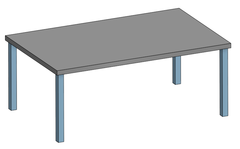
I created a simple table with four table legs and a table top. Which part should I fix to create a simulation?

So I create a floor, which means I have to create a new part in a new part studio. Then I have to assign a material to the floor to be able to run the simulation. Even the floor is not moving or deforming. Then I add the floor to the assembly which changes the total mass of the assembly. And the floor is changing the BOM because it is a new part.
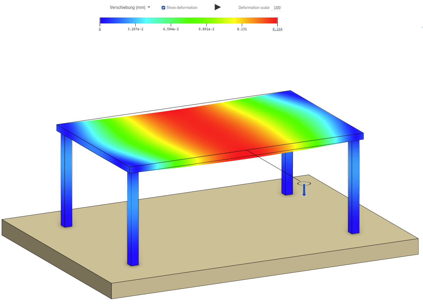
Finally I have a running simulation of the table with a floor:

But you can see that all legs are sticking to the floor and they are not sliding. This artificially increases the stiffness of the table.
Normally I would have fixed only the lower surface of one leg. The other three legs should be able to slide over the surface.
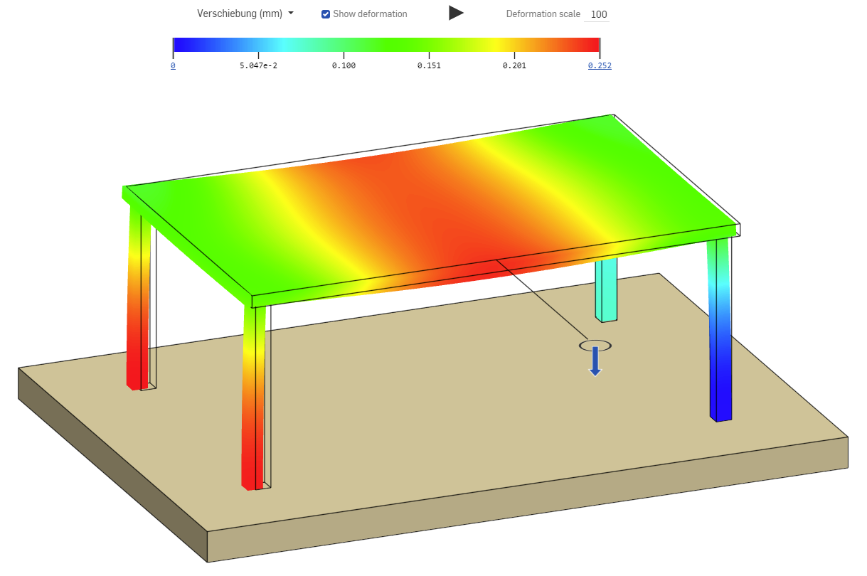
So I create three new planar mates at the bottom of the legs:

 Now the legs can slide on the floor and I get a better result. (An even more accurate result would be the legs could only transfer pressure forces.)
If Onshape users could define boundary conditions in a similar way like they define the loads.
I could have made the simulation in the original table assembly, without the following:
What do you think? Is there a plan to introduce new commands to create boundary conditions?
But in my opinion there is a problem that we can't create boundary conditions.
At the moment we have to fix one part of the assembly, so we don't have rigid body motions in the simulation.
I created a simple table with four table legs and a table top. Which part should I fix to create a simulation?

So I create a floor, which means I have to create a new part in a new part studio. Then I have to assign a material to the floor to be able to run the simulation. Even the floor is not moving or deforming. Then I add the floor to the assembly which changes the total mass of the assembly. And the floor is changing the BOM because it is a new part.
Finally I have a running simulation of the table with a floor:

But you can see that all legs are sticking to the floor and they are not sliding. This artificially increases the stiffness of the table.
Normally I would have fixed only the lower surface of one leg. The other three legs should be able to slide over the surface.
So I create three new planar mates at the bottom of the legs:

 Now the legs can slide on the floor and I get a better result. (An even more accurate result would be the legs could only transfer pressure forces.)
If Onshape users could define boundary conditions in a similar way like they define the loads.
I could have made the simulation in the original table assembly, without the following:
- Creating a new part-studio to create a floor part
- Inserting the floor in the assembly, which changes the total mass and the BOM. (This could also make trouble if I would make a Release Candidate, because the floor would require a part-number)
- Changing the fixed part to floor
- Creating new mates between the legs and the floor
What do you think? Is there a plan to introduce new commands to create boundary conditions?
0
Comments