Welcome to the Onshape forum! Ask questions and join in the discussions about everything Onshape.
First time visiting? Here are some places to start:- Looking for a certain topic? Check out the categories filter or use Search (upper right).
- Need support? Ask a question to our Community Support category.
- Please submit support tickets for bugs but you can request improvements in the Product Feedback category.
- Be respectful, on topic and if you see a problem, Flag it.
If you would like to contact our Community Manager personally, feel free to send a private message or an email.
Work flow Friday. sheet metal and lofts.
 robert_stiles
Member Posts: 159 PRO
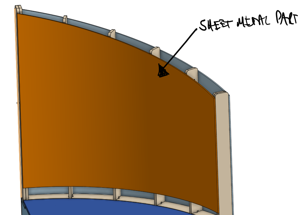
Hello, I have a working workflow (!?) but I'm not convinced its the most efficient. I think I'm missing something. Surfaces, lofts and sheet metal are not areas of Onshape I know massively well, so I thought I might ask for some best practice advice. I need a shape like this.

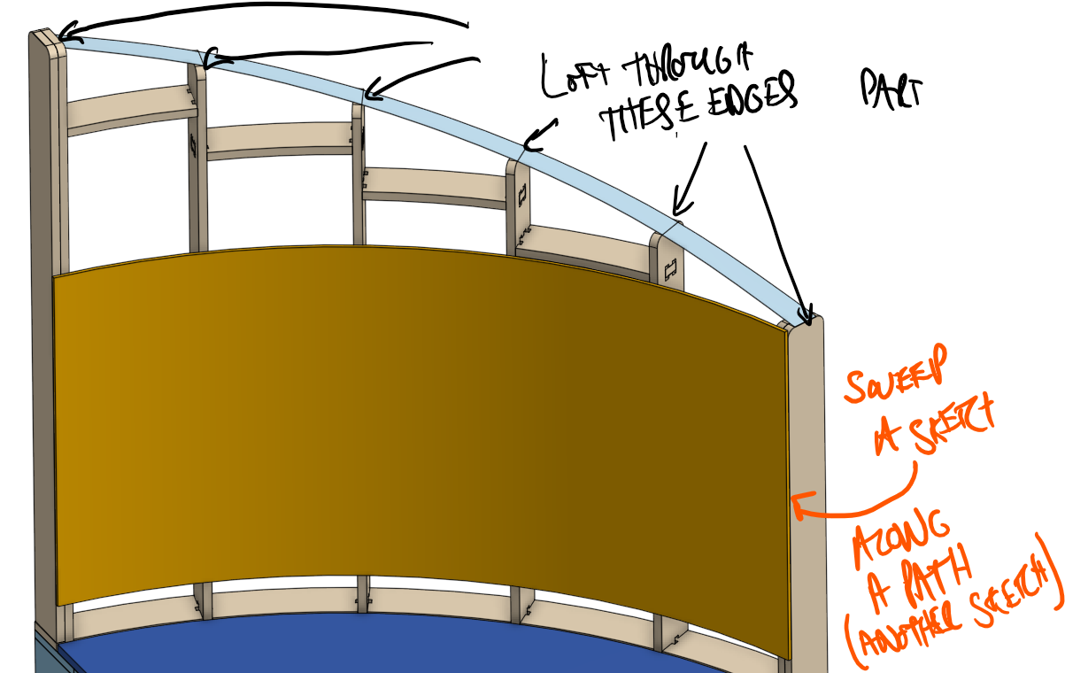
Its working, but I think I'm hacking it - there must be a cleaner way. I have to make a sweep and a loft


to bring the sweep up, I am using Replace face (not a feature I use much, thanks to some advice on another project here on the forum! thankyou ! ), selecting the top face of the sweep up to the loft as the face, then create a sheet metal part, using thicken, from one of the faces of the adapted sweep. But then I have to delete the original sweep, and the loft. It all feels like I'm creating lots of parts to delete them again.
I wanted to start with a lofted surface instead of the face of the adapted sweep part, but it seems sheet metal parts can only be made from co planar, cylindrical, or extruded faces. I assumed that this loft surface which I tried starting from should be a cylinder... but I guess I'm not creating it in the correct way. I can create a ruled surface from an arc (definitely a cylindrical face), but then I fail to extrude this to the top helical surface.
Any thoughts?
Thanks
Rob


Its working, but I think I'm hacking it - there must be a cleaner way. I have to make a sweep and a loft


to bring the sweep up, I am using Replace face (not a feature I use much, thanks to some advice on another project here on the forum! thankyou ! ), selecting the top face of the sweep up to the loft as the face, then create a sheet metal part, using thicken, from one of the faces of the adapted sweep. But then I have to delete the original sweep, and the loft. It all feels like I'm creating lots of parts to delete them again.
I wanted to start with a lofted surface instead of the face of the adapted sweep part, but it seems sheet metal parts can only be made from co planar, cylindrical, or extruded faces. I assumed that this loft surface which I tried starting from should be a cylinder... but I guess I'm not creating it in the correct way. I can create a ruled surface from an arc (definitely a cylindrical face), but then I fail to extrude this to the top helical surface.
Any thoughts?
Thanks
Rob

0
Comments
I'm guessing you aren't able to move the top edge of the sheet metal to the lofted face as it would violate the "normal to thickness" if you create sheet metal part first.
The way I would approach this would be to create a sheet metal part first but make it go to the tallest part, then do a swept cut along the helical path (or maybe a lofted cut, should work either way) to trim the top edge. This "should" be able to cut the top while keeping it "normal" as required for sheet metal. This should work better than trying to extend the sheet metal after the fact...
Alternatively, you might be able to just create the circular arc surface, trim/extend to your lofted top cap and then use a "thicken" to create the sheet metal at the end. This way you don't need to worry about the "normal cut" part as you create the overall shape. Basically similar to what you are doing but using just a surface instead of creating a solid and using just one side of it (less "discarded" stuff).
create a sheet metal part first....then do a swept cut along the helical path (or maybe a lofted cut, should work either way)
How would you do these cuts?? which feature?
Alternatively, you might be able to just create the circular arc surface, trim/extend to your lofted top cap
Again, what feature are you using to trim extend?
Are you creating a part first? is this the missing step? I'm trying to do it all to that top loft surface and its not picking it up??
Thanks so much
Note that I created the top surface as a helical sweep but it could be a loft instead, however you would have to create profile sketches for each one so probably not the best option.
Also note that Onshape does require the base shape of a sheet metal part to be either planar or cylindrical so best to create it using arcs/revolves etc (rather than a loft/sweep even if the result is theoretically a cylinder as it might not recognize it as such...)
Also, your original workflow wasn't "bad" by the way, it's just generally slightly cleaner to use surfaces for "construction geometry" rather than parts (although there are exceptions to that for sure!).
I generally prefer to create larger things and trim them rather than smaller and extend as it tends to be more "reliable" bit the way you have the geometry setup, the easiest would probably be to just create a simple circular surface and use the "move boundary" option to bring it to your lofted "top limit" (i.e. the 3rd option the example) so very similar to what you did but with a surface instead of a solid/replace face...
In the above document, there were two items deleted. A surface used to wrap to, and a part used as a path.
There are 2 Part Sudios
The first does not have the double studs because I wanted to clearly show how the top of the studs intersect the top of the raked panels. The rake being the slant at the top of the panels
Minimizing the number of features in the feature tree, can certainly be considered a step towards making a document more efficient
In Part Studio 1, it took 21 features or 21 steps to make the entire wall with bottom plate, studs with fillets, blocks, and panels
Part Studio 2 took two extra steps because of the double studs at both ends
- Move boundary is a feature I saw in an update a while back, but I'd kind of forgotten about.
- Wrap (and the feature script of wrap and thicken!, very nice) is another feature I really need to get to grips with, as I think I want to soften the rise as it peaks. This will give me more control than the helix.
Like I say, a lot here for me to get my head around.
Thanks again.
I noticed you had some method of connecting the studs to the bottom plate and similar @ blocks to studs. I decided to stay away from that.
Those connections don’t look substantial enough to me. As best I could see from the image, having that one point of connection, in the middle of the stud or block, means you have a pivot
Myself — I probably would use either two dowels or two screws at each of those location. Meaning that each block would have two screws at each end, and each stud would have two screws from bottom plate to stud. And everything would’ve been pre-drilled also
Now it was a little hard for me to tell what you wanted at the end studs. It looked like you might want the paneling to wrap around those end studs, but you just weren’t showing it. That’s why I had the paneling stick out past the face of the end studs
Now if there was to be no paneling on the ends, and if you didn’t want screwheads to show, then you could countersink and furnish plugs
You are quite right, but I'll direct message you with an explanation if you like, its not really Onshape stuff, just joinery talk !. This is actually all framing for seating, and it gets covered by the upholsterer, from a joiners perspective the frame work is super quick and dirty compared to our staircases.
A similar but differnt seating project we did here, but you will get the idea.