Welcome to the Onshape forum! Ask questions and join in the discussions about everything Onshape.
First time visiting? Here are some places to start:- Looking for a certain topic? Check out the categories filter or use Search (upper right).
- Need support? Ask a question to our Community Support category.
- Please submit support tickets for bugs but you can request improvements in the Product Feedback category.
- Be respectful, on topic and if you see a problem, Flag it.
If you would like to contact our Community Manager personally, feel free to send a private message or an email.
Lofting problem wing with gurney flap
 robert_horton034
Member Posts: 6 ✭
in Drawings
I'm creating a wing shape that will be 3d printed. It helps a lot to have a flat edge which will be the side that lies down on the bed of the printer. I've lofted the wing shape and I'm using the trailing edge of the wing to be the edge that lays on the bed. This way the entire wing can be printed without support. So far so good.
A print needs a decent surface area to successfully print; something for that first layer to attach to the bed. Since the trailing edge of the wing is very thin, I'm adding a sizable gurney flap onto that wing trailing edge so that the print has a decent-sized contact with the bed.
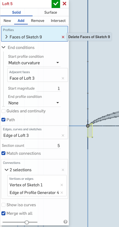
Where I run into a problem is in lofting the gurney flap so that it matches and connects to the lofted wing profile.
https://cad.onshape.com/documents/79305a673201200f8bc2a108/v/2f456a921951e6c48334788d/e/87dce962878413a7ad0544d6
I've been through the reference guides, the tutorials, and a variety of videos. The loft of the wing works fine but connecting it to the gurney flap has me stumped. I can't find any way to make the wing profile include the gurney flap. I spent several weeks on that attempt. 2d drawings can't be merged into a part. Every time I attempt to loft either the wing profile or the gurney flap as separate lofts that I will then use binary to merge fails because I can't get any lofts to follow a guide or a path. I created a 3d spline that matches the trailing edge but it refuses to use the spline as the path.
Above is the wing profile with the gurney flap.

And this is where I get stuck attempting to loft the flap.
A print needs a decent surface area to successfully print; something for that first layer to attach to the bed. Since the trailing edge of the wing is very thin, I'm adding a sizable gurney flap onto that wing trailing edge so that the print has a decent-sized contact with the bed.
Where I run into a problem is in lofting the gurney flap so that it matches and connects to the lofted wing profile.
https://cad.onshape.com/documents/79305a673201200f8bc2a108/v/2f456a921951e6c48334788d/e/87dce962878413a7ad0544d6
I've been through the reference guides, the tutorials, and a variety of videos. The loft of the wing works fine but connecting it to the gurney flap has me stumped. I can't find any way to make the wing profile include the gurney flap. I spent several weeks on that attempt. 2d drawings can't be merged into a part. Every time I attempt to loft either the wing profile or the gurney flap as separate lofts that I will then use binary to merge fails because I can't get any lofts to follow a guide or a path. I created a 3d spline that matches the trailing edge but it refuses to use the spline as the path.

Above is the wing profile with the gurney flap.

And this is where I get stuck attempting to loft the flap.
0
Comments
https://cad.onshape.com/documents/12b0679a712bc6f544f72c07/w/67e973d9c8c7d9393a467fa0/e/966b75c44db58304ecde3538
https://cad.onshape.com/documents/582ef5bc0951a193050d44af/w/a2d2f9dbc29bf56356973493/e/ccc3374051443f8eb3b5b6d2
What I learned in that play area was that line or spline for the path must be a real line, not a construction line. I'm not sure why that restriction but that solved most of the problem. That solved it in the test drawing but not in the complex drawing I was working on. I'm going to try again to create a 2D profile with the gurney flap included since I know that works.
https://cad.onshape.com/documents/3adda7bee6878142e772d11e/w/8b312ac02139b14f7d8a1779/e/4bf239e7e1293ba383ac7073
Change profile generator to upper & lower splines.
The gurney strut on outboard end is now a simple sweep. This sketch shows the difference between tailing edge profiles.
https://cad.onshape.com/documents/3adda7bee6878142e772d11e/w/8b312ac02139b14f7d8a1779/e/4bf239e7e1293ba383ac7073
1. Include outline of gurney flap in your loft profiles. This way you will avoid the necessity to attach flap to a blade and make all in one loft.
2. Make a straight line along trailing edge and use it as guide in blade loft. When defining gurney flap assure that its edge with be exactly along blade trailing edge and make it so its body sufficiently embedded inside the blade. This will guarantee flap to blade attachment.
What I did, in the end, is to trace the profile with the spline tool including the gurney flap that I wanted; as leonid_raiz suggested. Maybe there is something in the UI that I am missing but there is a serious lack of error message feedback to the user. I would not accept a code compiler rejecting my code with the only clue being "error". At the minimum, I would expect an error code I have to go look up in a book. I don't see why a CAD tool should be much different. Getting a clue as to what the problem seems to be the number one stumbling block to many operations.