Welcome to the Onshape forum! Ask questions and join in the discussions about everything Onshape.

First time visiting? Here are some places to start:
  1. Looking for a certain topic? Check out the categories filter or use Search (upper right).
  2. Need support? Ask a question to our Community Support category.
  3. Please submit support tickets for bugs but you can request improvements in the Product Feedback category.
  4. Be respectful, on topic and if you see a problem, Flag it.

If you would like to contact our Community Manager personally, feel free to send a private message or an email.

Options

Creating a plane through two axis

leecaseyleecasey Member Posts: 34 PRO
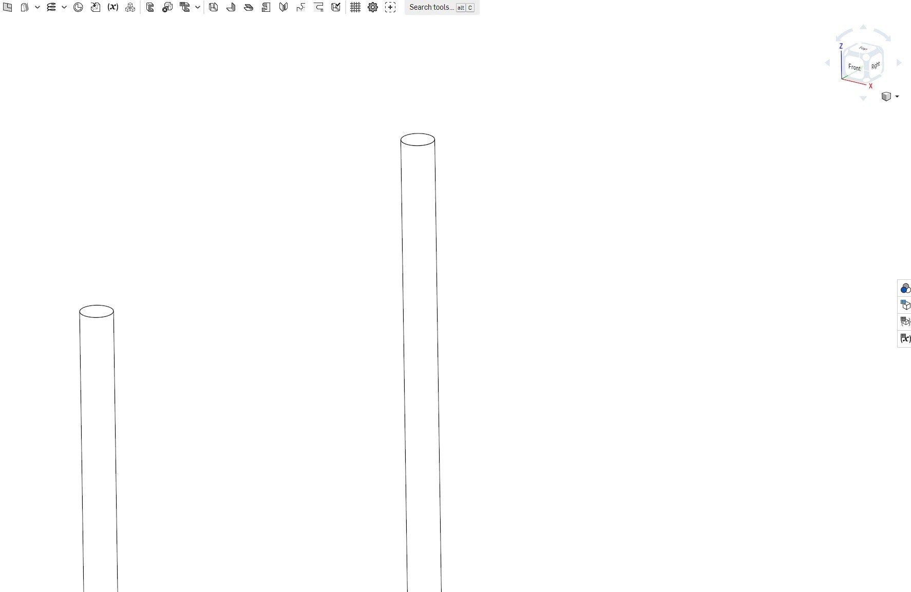
Hi, I'm trying to create a plane through the axis (which don't exist) of these two bars. I am coming from Creo so I'd probably just create an axis and then make it parallel to right right datum plane. However, I'm struggling to figure out how I do that here. Whats the correct procedure? 

Comments

  • Options
    eric_pestyeric_pesty Member Posts: 1,549 PRO
    I think the quickest way to get that would be to create a sketch on one of the cylinder ends and draw a line going to the center of the other cylinder, maybe add a line segment normal to that to be able to fully define the plane (or depending on what you need to do you can probably use one of the sketch mate connectors directly.
  • Options
    bruce_williamsbruce_williams Member, Developers Posts: 842 PRO
    another way is to just add Mate connectors to 3 ends and then make 3 point plane.  Mate connectors are powerful little guys.
    www.accuratepattern.com
  • Options
    steve_shubinsteve_shubin Member Posts: 1,069 ✭✭✭✭
    @leecasey

    @eric_pesty and @bruce_williams both give great solutions

    Here is an additional method

    https://cad.onshape.com/documents/e63bac33aa02ae125fad2571/w/e4cc1a84322b70940d0821ef/e/c72dc97e4ae3d3b38cb85758

    The plane is created through the use of the MultiMateConnector featurescript
    I created the sketch using the mate connector as the plane, in order to show how the rectangle was on plane with both axes


  • Options
    eric_pestyeric_pesty Member Posts: 1,549 PRO
    edited December 2022
    @steve_shubin
    I did not realize MutliMateConnector could "figure out" a direction from two cylindrical faces like this! Good to know!

    The "standard" mate connector really needs to have more options (i.e. most of the MMC one)!
  • Options
    steve_shubinsteve_shubin Member Posts: 1,069 ✭✭✭✭
    @eric_pesty

    MultiMateConnector - I really like that tool
  • Options
    leecaseyleecasey Member Posts: 34 PRO
    Hi Eric, to draw a sketch as an axis would need a plane through the rods which is what I’m trying to achieve. I could offset from the right plane but I didn’t want to do that as every time I increase the size I’ll have to remember to move the offset datum. I’m new to Onshape so not sure if relations exist. I’d really like to be able to add data I’m axis. I’ll check feature requests. 
  • Options
    _anton_anton Member, Onshape Employees Posts: 295
    edited December 2022
    Another idea: if you know the offset (distance and direction) of the rod centerlines, you can store the distance in a variable and use that: https://cad.onshape.com/documents/a03b23fd4ec3531ddf74f508/w/60b41b970c913f494b48ac3e/e/f965f86d2b31a079fcf9a2a2

    (The sketch here is made using an implicit mate connector relative to the origin, realigned normal to the right plane, and shifted along z by the distance variable.)
  • Options
    eric_pestyeric_pesty Member Posts: 1,549 PRO
    @leecasey
    I meant from a top view:


  • Options
    dirk_van_der_vaartdirk_van_der_vaart Member Posts: 543 ✭✭✭
    Here's a basic solution, create a 3d spline between two sketches and then use Line Angle Plane
    https://cad.onshape.com/documents/fbfb9c3a24ccea2919687b0b/w/27d5b6e42501dcb681a7190f/e/9018839cdf09db6127a9d793

  • Options
    eric_pestyeric_pesty Member Posts: 1,549 PRO
    @leecasey
    If you have at least one point on the centerline of the one of the cylinders, you can actually use the curve/point plane option like this:


  • Options
    steve_shubinsteve_shubin Member Posts: 1,069 ✭✭✭✭
    edited December 2022

    MultiMateConnector can be a little tricky to use

    In the GIF above, here is the order of things

    1. DEFINITION TYPE - Centroid
    2. Then click on cylindrical face of cylinder “A”
    3. PRIMARY AXIS DEFINITION - Face normal
    4. Then click on cylindrical face of cylinder “B”
    5. SECONDARY AXIS DEFINITION - Face normal
    6. Then click on cylindrical face of cylinder “A”
    7. Click on CONSTRUCTION
    8. Click on ADD TRANSFORM
    9. Set ROTATE Y (rotY) to  90°
    10. Click on Green checkmark

    You now have a Mate Connector that can act as a plane for a sketch

    Note that clicking on CONSTRUCTION, reveals or shows the mate connector

    Also note that whichever part you use for Centroid in DEFINITION TYPE, well that also needs to be used for SECONDARY AXIS - and the PRIMARY AXIS is to be the other cylinder.


Sign In or Register to comment.