Welcome to the Onshape forum! Ask questions and join in the discussions about everything Onshape.
First time visiting? Here are some places to start:- Looking for a certain topic? Check out the categories filter or use Search (upper right).
- Need support? Ask a question to our Community Support category.
- Please submit support tickets for bugs but you can request improvements in the Product Feedback category.
- Be respectful, on topic and if you see a problem, Flag it.
If you would like to contact our Community Manager personally, feel free to send a private message or an email.
Simulating beam deflection with free ends
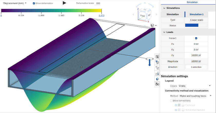
Howdy folks. I'm playing around with the new simulation tools and started out with a simple beam deflection example. I got a "fixed end" solution up and running in minutes, but then spent a considerable amount of time trying to get it to solve a "free ends" model.
I was hoping I could just leave that top plate unconstrained and just allow OnShape to use contacts to figure out the "hinge" around which the material would bend, but no luck.
I tried a bunch of different configurations of mates too. I feel like a pin and slot at each end makes the most sense, but it still wouldn't solve.
Here's the document: https://cad.onshape.com/documents/d2440289f8117f7ffc496a11/w/3a480f7e650f42f3f0cf5455/e/710ba9a85c170463c8b0a1a8
Thanks in advance!
Here's the fixed end example:

1

Comments
The following Mates are not translated, and therefore, not supported by simulation: Tangent Mate, Pin Slot Mate, and Parallel Mate. Relations (Gear relation, Rack and pinion relation, Screw relation, and Linear relation) are also not supported.
Simon Gatrall | Product Development Specialist | Open For Work
In terms of achieving this "free ends" model, in general you need a statically determinate assembly for Onshape to solve. For instance, using the "Mates" method with the top plate unmated, you have rigid body motion and cannot converge. Additionally, Pin-Slot mates are not currently supported by simulation.
The approach I would take here is to put a revolute mate on the edge that is the "hinge". Note though, that that mate applies to all faces of the part in contact, or very close to being in contact. So if you truly wanted the outside edge to lift up, you'd need to use a simulation connection (see section below this) to specify that you only want that revolute mate connection to apply just around the edge.
I tried a single revolute mate on one side (without the helper parts) and it won't converge. If I add two revolute mates, it solves, but it glues the ends down and stretches the middle. This isn't what I think @stusona is asking for.
Simon Gatrall | Product Development Specialist | Open For Work
I also tried adding the "simulation connection" selections to the mates. It didn't seem to help.
Simon Gatrall | Product Development Specialist | Open For Work
Yea I tried configurations like the single hinged revolute and had the fastening issue Simon is showing. And I tried with/without checking the "simulation connection" checkbox in the relevant mates as well. Though I didn't explore the "show connections" very well. That's helpful!
Got what I'm looking for: free end deflection! The max deflection formula predicted 12.35 mm, so 10.1 mm is pretty reasonable.
Can't wait to play around with the tool in the future.
Simon Gatrall | Product Development Specialist | Open For Work
And I see that I mis-evaluated the original ask, of allowing the top plate to slide on the "hinged" contact. That cannot be achieved with the simulation connection, you will need a second mate/body. I was trying to help allow the edges of the plate to lift up and not be fused to the top face, but your solution is much more appropriate here.