Welcome to the Onshape forum! Ask questions and join in the discussions about everything Onshape.
First time visiting? Here are some places to start:- Looking for a certain topic? Check out the categories filter or use Search (upper right).
- Need support? Ask a question to our Community Support category.
- Please submit support tickets for bugs but you can request improvements in the Product Feedback category.
- Be respectful, on topic and if you see a problem, Flag it.
If you would like to contact our Community Manager personally, feel free to send a private message or an email.
Best practice to create a model from technical drawings
 gauthier_östervall
Member Posts: 99 ✭✭
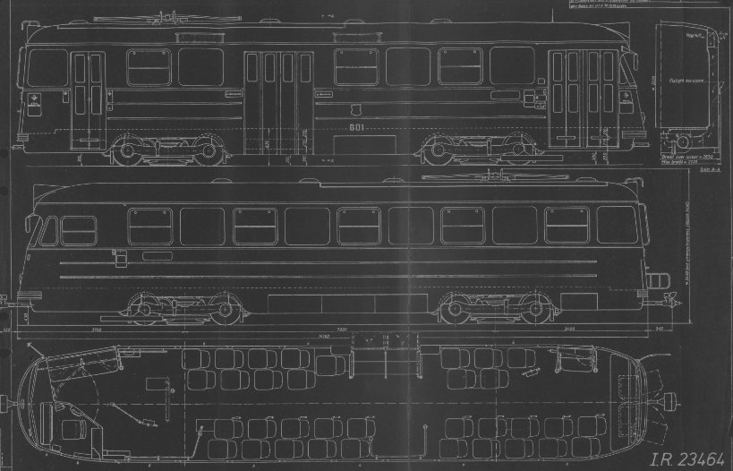
I have the technical drawing for a tramway, from which I would like to create a 3D model. I have the front view, side view, top view.
What would a good method be, to create the 3D model from the drawing?
My naive approch would be to import the images, place them in sketches in relevant planes, draw a sketch over the drawing, then Extrude-Intersect a blob with these three sketches.
The drawing looks like this (I have the front view as well, it's very simple):

I see already that it will probably fail to make correct corners.
What would be the rough steps you would take, to create such a model?
What would a good method be, to create the 3D model from the drawing?
My naive approch would be to import the images, place them in sketches in relevant planes, draw a sketch over the drawing, then Extrude-Intersect a blob with these three sketches.
The drawing looks like this (I have the front view as well, it's very simple):

I see already that it will probably fail to make correct corners.
What would be the rough steps you would take, to create such a model?
Tagged:
0
Comments
Hi @gauthier_östervall, you are right. Intersecting will not give you the rounded look that this drawing has. There are quite a few different ways to go about this, it will depend on how exact you want to match the drawing.
Here are some steps if you just want a quick model that looks like it:
If you are going for a more exact approach, you will most likely need to create guide sketches and preform several lofts for the main body. Create sub assemblies of all of the parts, then assemble them into a main assembly.
What is your end goal? A quick model, or production ready?
Learn more about the Gospel of Christ ( Here )
CADSharp - We make custom features and integrated Onshape apps! Learn How to FeatureScript Here 🔴
The real end goal for that specific model is to 3D print small miniatures for a board game. So not at all an exact approach.
BUT, this is not the first time I ask myself this question, so I wanted to take the opportunity to learn how to do it "the right way".
When you write "Create sub assemblies", do you mean a Part Studio per such sub assembly, then put together in an actual Assembly tab? And do you mean for the details, or even split the main body into sub-parts?
I see, then there are still different options to approach it. For 3D printing miniatures, you will not need an assembly with incredible detail. You can simply have one Part studio with one part, since the miniature will most likely be one piece I assume.
See the Cyber truck example in the Intersect Views document. It shows how to split the parts faces for details. After the faces are split, you can Thicken them for printable detail. This is a great example for a printable part. Intersect views custom feature wont work perfectly for this train, as your train has rounded parts.
Learn more about the Gospel of Christ ( Here )
CADSharp - We make custom features and integrated Onshape apps! Learn How to FeatureScript Here 🔴