Welcome to the Onshape forum! Ask questions and join in the discussions about everything Onshape.
First time visiting? Here are some places to start:- Looking for a certain topic? Check out the categories filter or use Search (upper right).
- Need support? Ask a question to our Community Support category.
- Please submit support tickets for bugs but you can request improvements in the Product Feedback category.
- Be respectful, on topic and if you see a problem, Flag it.
If you would like to contact our Community Manager personally, feel free to send a private message or an email.
Need help making a 2 part housing (loft? derived?)
 benj_fitzpatrick
Member Posts: 13 ✭
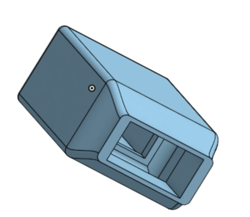
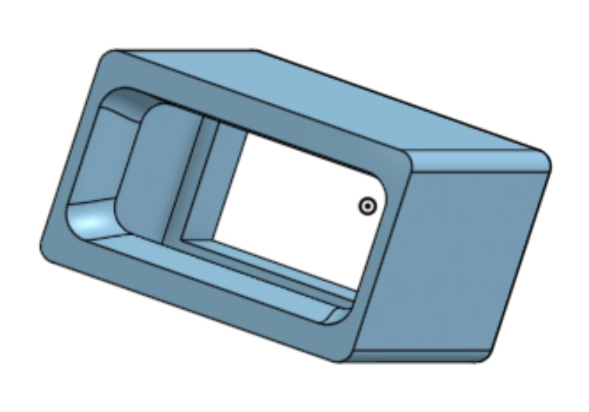
I am trying to make a housing for a temperature readout (Omega CN32PT) and would like to have it split in half front to back to make it easy for setting up the power and T probe connections at the back of the readout (eventually this will be fabricated on a 3D printer). The front has a recess for the display and the back has a power entry module and an opening for the temperature probe (RTD). I used a loft to create parts that can hopefully mate, but the loft curves which is not ideal.
I would like to have these mate up with some means for screwing them together that does not stick out horribly. What thoughts do you have for how to create a better mate between the two parts?


0
Answers
https://www.ebay.com/itm/374432590552?mkcid=16&mkevt=1&mkrid=711-127632-2357-0&ssspo=OHp8breNTem&sssrc=2349624&ssuid=5oWsg52nQJW&var=&widget_ver=artemis&media=COPY
Have you considered a clamshell design? That’s usually how electronics are enclosed, especially something as long as this. You could have a half-lap joint around the perimeter on the parting line. On the back side, you could have the parting line on the mid line of the connectors. Or, have a separate piece as a back panel for the connectors to pop through.
https://cad.onshape.com/documents/1cb6823e7f9cd5a4abab5faa/v/b071110563b323ab063b8511/e/8b342e137c2a629dc11c85b5?explodedView=MmxDspVvE1k6gH09H&renderMode=0&rightPanel=explodedViewPanel&uiState=6408fdd9ba1cc50600d025c5
A few things of note:
-Clamshell design (means a bottom and a top, separated roughly in the middle). Most common design for injection molding an electronic enclosure.
-A half lap around the perimeter. Keeps the halves aligned.
-Omega electronics part represented as a rectangle. The box is built around it parametrically.
-Ribs to support the omega part (I did not see any screw holes in it on the pictures, but if there are, I'd probably use those instead).
-Ribs have .5mm of clearance to the part. You would fine tune their clearance in the CAD to get the right fit. In injection molding this is very important as you can't move the box walls once the mold is made, but you can make the ribs taller. In printing, you could alternatively just make the box bigger or smaller each print.
-The sides of the box are wider than the omega. This allows room to put 4 screw bosses. The head of the screw would be on the bottom, and the screw would thread into the top. (bosses not modeled).
-Openings in the front and the back for the LED, the PEM, and access to get to the screw for the wire.
You could also put a screw in instead of a detent (in the same direction as the detent). That will keep the design pretty on the outside. A snap finger could also work. I guess it depends how frequently you would want to access the internals.