Welcome to the Onshape forum! Ask questions and join in the discussions about everything Onshape.
First time visiting? Here are some places to start:- Looking for a certain topic? Check out the categories filter or use Search (upper right).
- Need support? Ask a question to our Community Support category.
- Please submit support tickets for bugs but you can request improvements in the Product Feedback category.
- Be respectful, on topic and if you see a problem, Flag it.
If you would like to contact our Community Manager personally, feel free to send a private message or an email.
Export as DXF - No Flanges?
 elizabeth_wolfe828
Member Posts: 9 ✭
Hi! I'm working on the following model: https://cad.onshape.com/documents/ffe8f1ea172551fbefe37f7f/w/a3bc4c7e495f126959455a22/e/ad5120d9f57c4db177336d9a
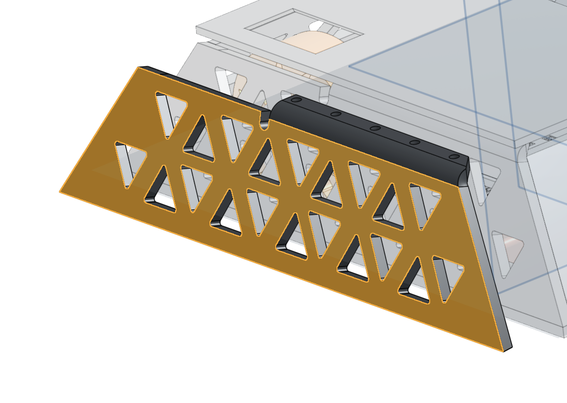
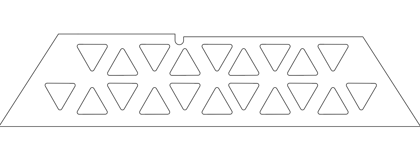
When I click the face of the sheet metal model + export as a DXF, it only exports one face, without the flange. Can anyone tell me why this is happening or how to fix it? Did I click off finish sheet metal model too early?


0
Comments
EDIT: it doesn't look like your model is public so I can't see what you are trying to do. Also regarding you second part, I don't see any reason why you would need to "finish" your sheet metal at all.
You only need to do this if you need to add features that aren't supported in an active sheet metal part (like dimples, louvers, etc...)
Simon Gatrall | Product Development, Engineering, Design, Onshape | Ex- IDEO, PCH, Unagi, Carbon | LinkedIn
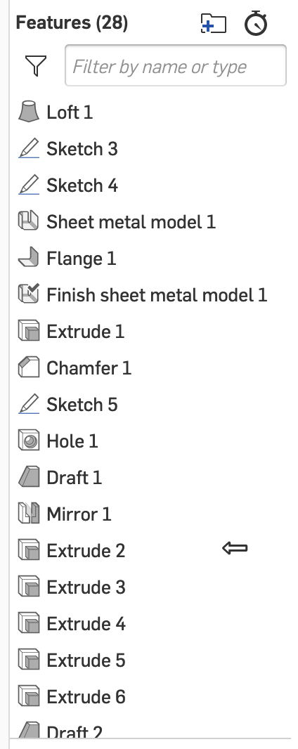
My recommendation would be to add as much of the features as possible before the "finish sheet metal" feature (i.e. everything you want to show up in the flat pattern).
This should include all the "cutouts" and then only add some chamfers/drafts as late as possible.
Note that you could simplify the feature tree quite a bit by extruding in both directions for extrude 2 and 7, as well as using a "move face" feature to add clearance instead of several "extrudes"
Something like this: https://cad.onshape.com/documents/c0225e34622840e730a2c761/w/c68eb8ce2dfeebfea4d98024/e/ce0ba65c533fea3360fe0044
Note that all the feature are now in the flat so you won't have full contact of the faces in the cutouts (which may or may not be acceptable depending on the design intent/assembly method).
As a side note, from a design perspective, it looks like you would need a lot of machining anyway to create all these "non flat" features so I am not convinced the one bend adds a lot of value to your overall design compared to using a separate bracket, not to mention it will be quite hard to fabricate.
The screwed on lid makes sense, what I meant to say was that the bent flange could have been a separate part fastened to the plate somehow. But since you are welding already, I would consider making it a welded tab instead as it would likely make the whole thing easier to build.
If these tabs were welded last you could leave a bit of slop so that they can be fixtured in the exact right spot so all the holes line up. Maybe even have them mounted to the lid part when you weld them in place to ensure a perfect fit!