Welcome to the Onshape forum! Ask questions and join in the discussions about everything Onshape.
First time visiting? Here are some places to start:- Looking for a certain topic? Check out the categories filter or use Search (upper right).
- Need support? Ask a question to our Community Support category.
- Please submit support tickets for bugs but you can request improvements in the Product Feedback category.
- Be respectful, on topic and if you see a problem, Flag it.
If you would like to contact our Community Manager personally, feel free to send a private message or an email.
After you copy a part edit becomes poor
 don_b
Member Posts: 152 ✭✭
don_b
Member Posts: 152 ✭✭
Where as this is a fantastic product in many ways it is missing some basic features ......if one is to modify part 1 of the sample ...part 2 changes....you can not edit part 1 only....to edit part 2 requires that you essentially rebuild part 2 from scratch....See my idea about a part owns the sketch and it is copied with the part for easy edit.
https://cad.onshape.com/documents/67b621172175ec77ca607f33/w/303859a18fe9fd7318879c5d/e/2b146c98035a6f38338ef6a5
https://cad.onshape.com/documents/67b621172175ec77ca607f33/w/303859a18fe9fd7318879c5d/e/2b146c98035a6f38338ef6a5
Tagged:
0
Comments
If you're trying to make a family of parts, you probably want to use configurations instead. If you need to replicate a few simple sketches, you could feature-pattern them, using their entities as reference for whatever changes you want to make. And, if you're just translating a part, it tends to be more correct (in the paradigm of parametric CAD) to just move the creating sketch instead.
If you need something more complicated, you could write a custom feature that replicates sketches as well.
Twitter: @BryanLAGdesign
This program is very extensive but that seems to be something any CAD program should be able to do without resorting to special programming on the part of the user or convoluted order of operation to "just edit a part"
Twitter: @BryanLAGdesign
I believe you are doing a lot of work "all in one part studio" but that might not be the best option based on what you are trying to achieve...
I have a felling you might be better served by using other "top down" design approaches like deriving in reference geometry (sketches, faces, or even bodies) or using assembly contexts.
As a general rule if you find yourself needing functionality that no one else is asking for, it might be a sign you are not using the tool in it's "intended way" and there might be better approaches...
Also if the rollback bar is "very complicated", you might want to take a look at this: https://learn.onshape.com/learn/course/introduction-to-parametric-feature-based-cad/what-is-cad/parametric-feature-based-cad?page=1
I've tried to come up with a better example of ways to use configurations, variables and "reference". It's a bit rough because I didn't spend much time on it but hopefully it gives you some usable ideas...
https://cad.onshape.com/documents/63ede05284ce595591bb58b9/w/c90c3f825e72564dfccfaf0c/e/316778b4dc2bd074d20d0bd1?renderMode=0&uiState=6438a33afe0fad7411cef349
If you look at this assembly, there are three instances of the "configured bracket". These parts are configuration of the same part so use the exact same features, which is a much better way of doing things than copying and modifying when you have variations of the same geometry. In this case I used configuration variables so that these are "infinitely adjustable". I could also have opted for a table generating a set number of parts of specific dimensions.
In this case I created a "reference" surface which was created as an in-context part from the assembly, which is itself controlled by the two layout sketches I imported (one for the root and one for the tip). To make things interesting I made it as a loft so the taper isn't constant.
I am using the "reference shape and measurement ref" part studio (which is where I initially created reference surface) to "read" the values to use for each bracket (based on the distance from the root, which is also set with a variable), I can then go and "edit configuration" of each bracket in the assembly and set the values based on the measured ones. This method is actually not "parametric" as I have to set these manually but that can sometimes be useful if you want more detailed control (see example gif below).
As another example I also created a quick and dirty example part using the same reference geometry derived into the "Moved reference example" part studio. In this case I use a transform to move the reference geometry (using a configuration variable again) and create the brace part (rather than move the part, move the reference so the origin of the part remains constant). When I insert the brace part in the assembly, I just have to mate it to the reference surface corner (using the mate connector I created in the part) and it will always be the correct size and at the correct location based on the configuration it is set to.
This is "true" parametric design where I can put a brace anywhere from drawing the part just once and I adjust one value to create a new one in a different spot. It's a little bit more work up front for a lot less effort down the road...
I think you are looking for the Derived feature
https://cad.onshape.com/help/Content/derived.htm?Highlight=Derived
https://learn.onshape.com/courses/master-model
I would need flat patterns and more massage of the part will be required although my thread on transform and edit sheet metal parts does have workarounds for that..... no criticism intended.
Your example shows a whole different work flow and philosophy ......its hard for old dogs to learn new tricks....
Thank you very much.
Twitter: @BryanLAGdesign
To retrieve a version to main. Select main in the version list. Right click on the version you want to retrieve and a menu will display. Select restore to main.
https://cad.onshape.com/documents/9e2e1b002f638eda4ef66d49/w/982beac394793812088a1db3/e/380910d584491a9e114e6a47
It probably is possible but I will do it when I export to my Autocad the flat pattern....very frustrating here
and those sheet metal parts were all designed in the part studio and if you could do them in individual part studios you are a better designer than I am
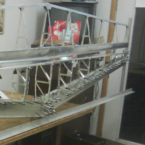
There is so much wrong with the entire model that I don't know where to start... A number of us have been trying to help by providing pointers on how to do this "properly" but if you insist on creating 100s of part with over a 1000 feature in a single part studio (including a bunch of redundant, broken ones), you are going to have a bad time!
Assuming we are talking about "sheet metal model 29" if you don't want some of the holes just create the part from sketch 428 (instead of the face of the solid) and select whichever faces you need, very simple...
And if you want to export a DXF with a specific alignment, just put that part into a drawing and use "align" view to pick a horizontal edge and export that. Also very simple.
If you are just doing a simple part you can get away with "freestyling" but not something like this. You are trying to design a complex assembly without first taking the time to understand the basic concepts of parametric CAD or following any of the best practice so it's no wonder it's not going smoothly!
If you would just go through the "top down" learning pathway in the learning center (and whatever other courses you need to get to the level where you can actually understand it), you could learn a number of different ways you could break this down into manageable chunks and design parts (or groups of parts) in separate part studios.
Basically this is like watching someone try to chop down a tree while holding the axe from the wrong end! Feel free to continue attempting doing this "your way" but please don't blame the tool if you are not willing to learn how to use it first!
I certainly will be able to massage the drawings in the Autocad in about 2 minutes
Sorry but the time invested in this drawing I feel I can save time by struggling rather than starting over ...
I would hope my struggles and comments might have helped the development of this platform as I still am very impressed ....