Welcome to the Onshape forum! Ask questions and join in the discussions about everything Onshape.
First time visiting? Here are some places to start:- Looking for a certain topic? Check out the categories filter or use Search (upper right).
- Need support? Ask a question to our Community Support category.
- Please submit support tickets for bugs but you can request improvements in the Product Feedback category.
- Be respectful, on topic and if you see a problem, Flag it.
If you would like to contact our Community Manager personally, feel free to send a private message or an email.
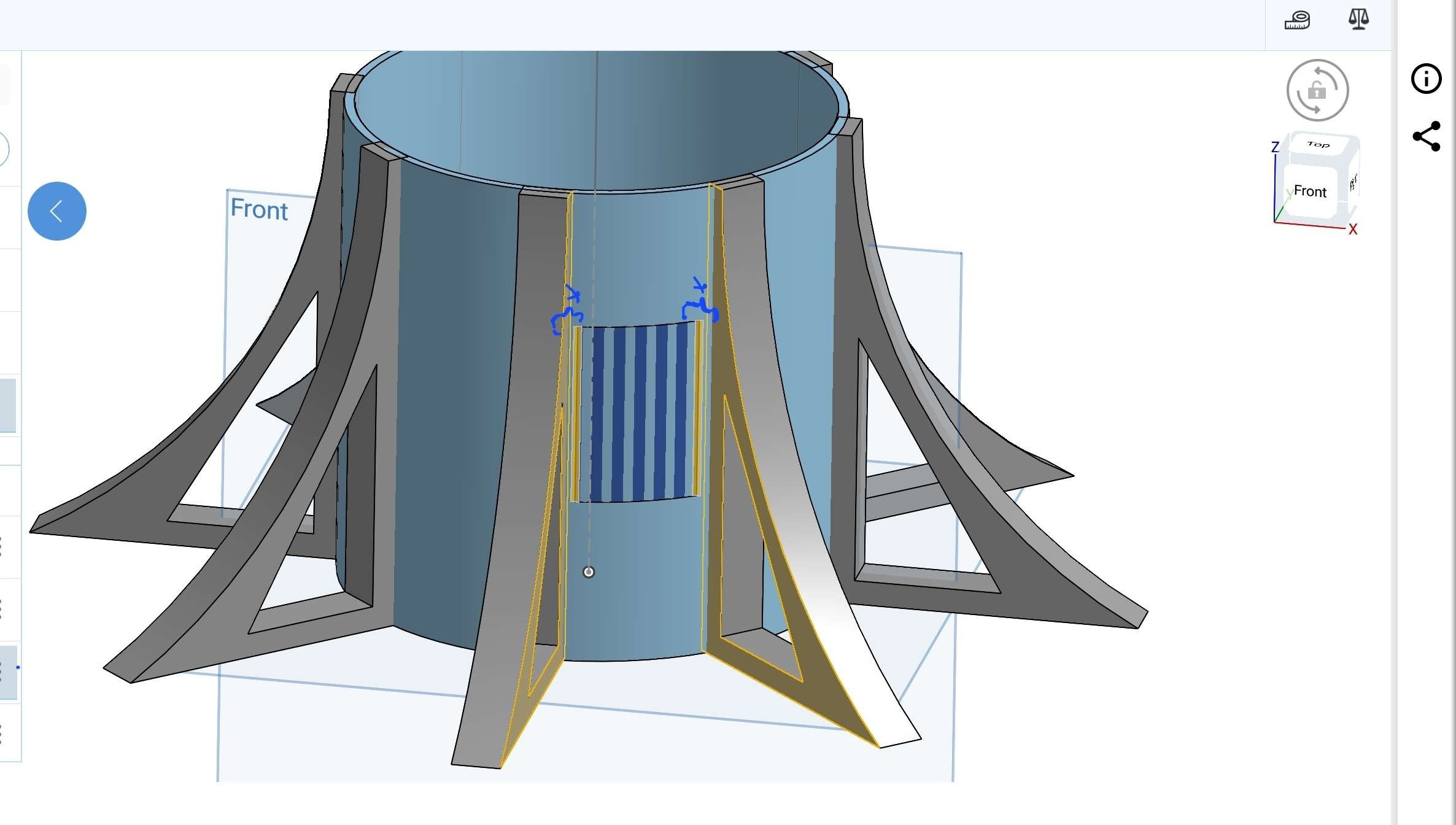
equal spaces of wrapped area between to parts
 Voyager
Member Posts: 19 EDU
Voyager
Member Posts: 19 EDU
Best Answers
-
 EvanReese
Member, Mentor Posts: 2,869 PRO
If it's as simple as a rectangle on a cylinder, I'd model this without wrap. Here are some thought starters. You could use:
EvanReese
Member, Mentor Posts: 2,869 PRO
If it's as simple as a rectangle on a cylinder, I'd model this without wrap. Here are some thought starters. You could use:- Revolve if you can calculate the angle
- Projected Curve and a Fill surface, Loft or Boundary
- Extrude from an arc to create a surface
- Split in "face" mode using a sketch
1 -
 S1mon
Member Posts: 4,077 PRO
If you put the sketch plane for the wrap at the bisector angle between the two gusset shapes, the wrap will stay centered on that area. If you want to explicitly control the X dimension, then some of Evan's suggestions are probably more straightforward. The video along with the help shows the sketch along a normal of the cylinder. https://cad.onshape.com/help/Content/wrap.htm?Highlight=wrap
S1mon
Member Posts: 4,077 PRO
If you put the sketch plane for the wrap at the bisector angle between the two gusset shapes, the wrap will stay centered on that area. If you want to explicitly control the X dimension, then some of Evan's suggestions are probably more straightforward. The video along with the help shows the sketch along a normal of the cylinder. https://cad.onshape.com/help/Content/wrap.htm?Highlight=wrap
Here's a quick example https://cad.onshape.com/documents/7d1a8c0d7cc107ea6a3eb68d/v/d425cdffc132ce701574714f/e/f2c8a592112b17d381a42f8a Wrap might be overkill with a simple cylinder and a pattern of rectangles. It really depends on what things you'll want to change in the future. If the rectangles are just a placeholder and you want to put some complex shape in that space then it makes sense that wrap might be useful.
Simon Gatrall | Product Development, Engineering, Design, Onshape | Ex- IDEO, PCH, Unagi, Carbon | LinkedIn
0 -
steve_shubin
Member Posts: 1,118 ✭✭✭✭
Using the wrap technique
Here’s how to adjust the clear distance AKA that X dimension.
1) Open up one of the CLEAR DISTANCE part studios.
2) Go into EDIT for Sketch 3
3) Adjust the upper dimension
 0
0 -
steve_shubin
Member Posts: 1,118 ✭✭✭✭
To set up the MultiMateConnector
1) Turn on —— CONSTRUCTION (for visibility during this setup)
2) Definition type —— CENTROID
3) Centroid origin —— EDGES OF CIRCULAR PATTERN (These are the 2 edges you’re going to center between)
4) Primary axis definition —— FACE NORMAL (so that the MMC faces the center of whatever you click on in step 5)
5) Primary axis reference faces —— FACE OF EXTRUDE (Click on the exterior face of the cylinder)
 0
0
Answers
The Onsherpa | Reach peak Onshape productivity
www.theonsherpa.com
https://cad.onshape.com/documents/a774efcb1a68c646c1ca5efb/w/b8af6d8e8b9ca25adcb88c27/e/641b99aed5dcd29b74dd68f7
But if you are still wanting to use wrap for some reason — read below
Use the MultiMateConnector (MMC) featurescript
Using this, you can center a MMC between the legs. And this MMC will act as a plane to sketch a rectangle, which can then be wrapped
When making the sketch for the rectangle, use the centerpoint rectangle and make the centerpoint of that rectangle coincident with the MMC
This way, if you adjust the thickness of your legs or the width of the rectangle in the sketch, that wrapped rectangle will keep the same clear distance at both of your ‘X’ locations
In the GIF, I adjust the thickness of the legs, and the sketch automatically adjusts around that
Make sure to look at all the part studios
One last thing. Make sure you look at all the settings for MMC and make sure you have construction selected otherwise you won’t be able to see the mate connector.
Here's a quick example https://cad.onshape.com/documents/7d1a8c0d7cc107ea6a3eb68d/v/d425cdffc132ce701574714f/e/f2c8a592112b17d381a42f8a
Simon Gatrall | Product Development, Engineering, Design, Onshape | Ex- IDEO, PCH, Unagi, Carbon | LinkedIn
Using the wrap technique
Here’s how to adjust the clear distance AKA that X dimension.
1) Open up one of the CLEAR DISTANCE part studios.
2) Go into EDIT for Sketch 3
3) Adjust the upper dimension
To set up the MultiMateConnector
1) Turn on —— CONSTRUCTION (for visibility during this setup)
2) Definition type —— CENTROID
3) Centroid origin —— EDGES OF CIRCULAR PATTERN (These are the 2 edges you’re going to center between)
4) Primary axis definition —— FACE NORMAL (so that the MMC faces the center of whatever you click on in step 5)
5) Primary axis reference faces —— FACE OF EXTRUDE (Click on the exterior face of the cylinder)