Welcome to the Onshape forum! Ask questions and join in the discussions about everything Onshape.
First time visiting? Here are some places to start:- Looking for a certain topic? Check out the categories filter or use Search (upper right).
- Need support? Ask a question to our Community Support category.
- Please submit support tickets for bugs but you can request improvements in the Product Feedback category.
- Be respectful, on topic and if you see a problem, Flag it.
If you would like to contact our Community Manager personally, feel free to send a private message or an email.
Give me an alternative to using screws.
 clayton_ertley
Member Posts: 58 ✭✭
in General
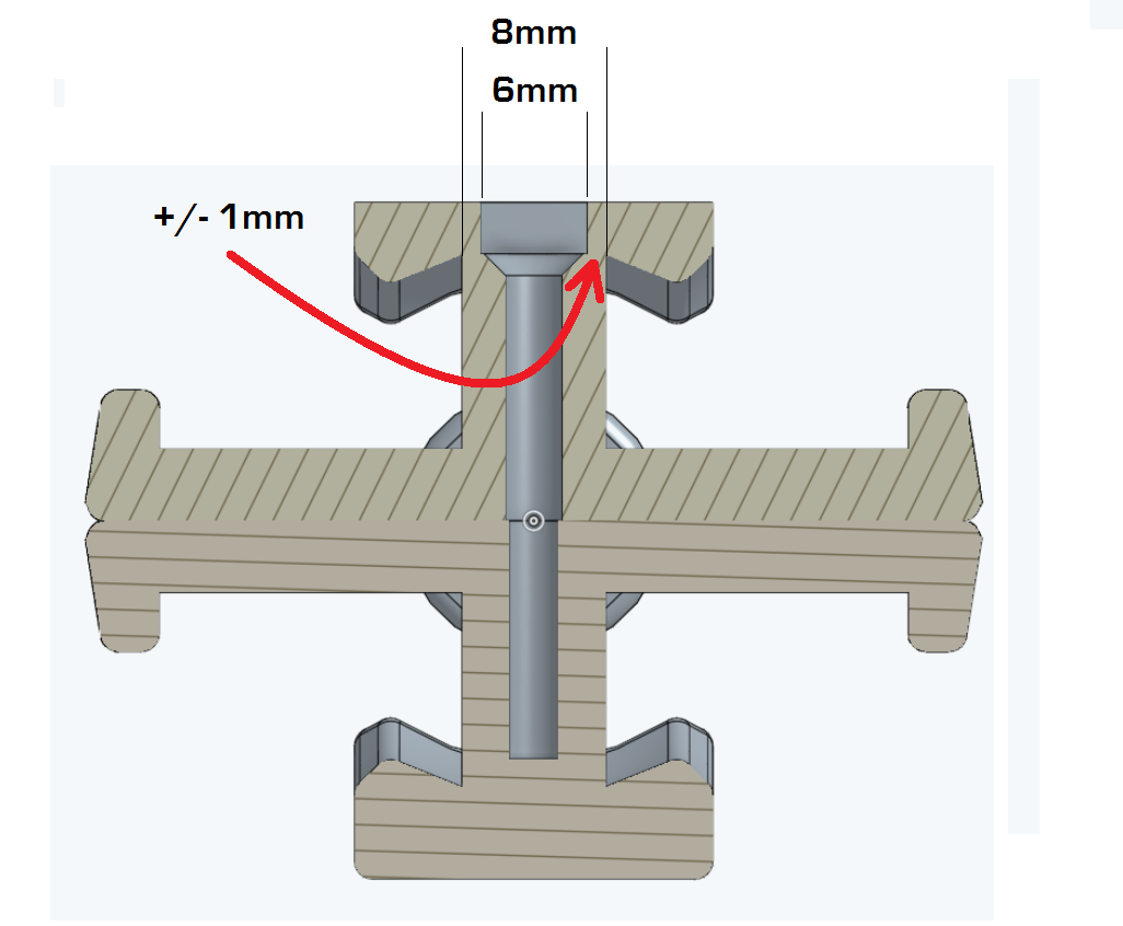
As some of you may know, I design and build twisty puzzles. Puzzle designers have long relied on using M3-M5 screws and tension springs for puzzles but are at times limited on space. I have made my document public so you can see my current issue and I have posted an image illustrating where the issue occurs. I am hoping some of the more experienced CAD users here can offer solution to this issue. Most twisty puzzle makers have not been to school for mechanical engineering and such. We are all hobbyist.
As seen in the image below, we are faced with an issue of structural weakness indicated by the red arrow. This is the general problem I am trying to address. I admit that there are work arounds that would allow me to continue use a screw like moving the taper section of the screw head UP about 2mm, but for the sake of the general issue, lets assume this is not possible.
Here are some rules that need to be followed:
1) Disassembling must not only be possible but simple and must not require breaking anything.
2) Must be 3D-Printable following Shapeways.com guidelines requiring no less than a .8mm thickness.
Here is sort of an extra goal/wish list of design features:
1) The ability to adjust the tension AFTER printing much like that of a screw( this can be extremely important for different puzzle designs.
2) The new core attachment mechanism be a separate object from both Core A and Core B so that in the case of damage the part is easily and cheaply replaced.
Thanks in advance for looking over my post. I look forward to reading your ideas.
https://cad.onshape.com/documents/85d2ce977199455098b1fb76/w/06ba472a547d40398cd0dd28/e/b96bea5b5e6a4c708de79f98

0
Comments
I don't see how it would help to fiddle with what's inside the envelope, because the size of that envelope seems to me to be dictated by the surrounding environment rather than its contents.
What I mean is that the thrust face (whether conical, as with the countersunk fastener you've been using, or flat, as with a panhead or cheesehead) must be of sufficient area that the plastic does not wear out prematurely.
This is true regardless of what's inside the envelope, and the more you try to cram in that fixed space, the harder it has to work.
I guess you could add a thin metal washer (perhaps bonded or keyed by its shape in place, so it does not rotate) to alleviate wear.
Hard to improve on the strength, simplicity, familiarity and fitness for purpose of a screw, unless there are other considerations you have not yet raised.
So I would stay with a screw, and look at two aspects:
1) using higher tensile strength steel so the shank can be a smaller fraction of the head diameter - this might allow the same thrust face area with a slightly smaller maximum diameter
2) Adding fillet radii to both the internal corners (one either side of your red arrow head). Sharp internal corners cause serious local intensification of stress, inviting cracking.
This second recommendation implies either
- reducing the outside diameter of the conical screwhead, (by turning it down cylindrically to remove the sharp corner, or scaling the whole head down)
- or profiling the sharp corner (with an external fillet) to match. The latter would not, I think, deliver a benefit sufficient to reward the expense.
If you need to go to a non-standard screw, try you local model engineering club for help with protoyping.
For production quantities, try someone like Misumi (assuming you're in the US)