Welcome to the Onshape forum! Ask questions and join in the discussions about everything Onshape.
First time visiting? Here are some places to start:- Looking for a certain topic? Check out the categories filter or use Search (upper right).
- Need support? Ask a question to our Community Support category.
- Please submit support tickets for bugs but you can request improvements in the Product Feedback category.
- Be respectful, on topic and if you see a problem, Flag it.
If you would like to contact our Community Manager personally, feel free to send a private message or an email.
Define the surface distance between two bending pockets
 Axel_Kollmenter
Member, pcbaevp Posts: 436 PRO
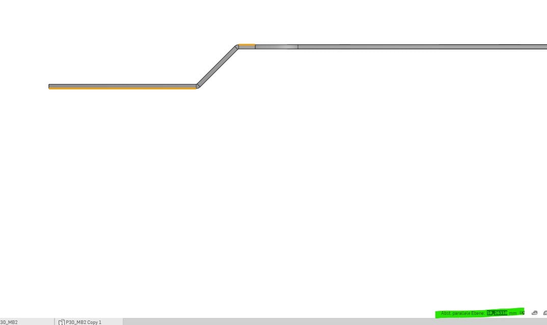
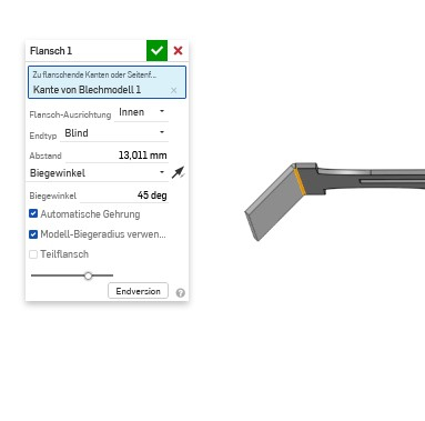
Is there a simple way to define the surface distance between two bending pockets if the angle is not 90°? In the following pictures, the distance between the two marked surfaces should be exactly 10.2 mm. At the moment, I am slowly adjusting the length of flange 1 until the surface distance is exactly right. This can go down to the fifth decimal place....
Of course I could build the sheet metal model differently from the beginning, but I already have some features planned in this part and no time to do it again. It would be ideal to be able to say afterwards what the distance between the two faces should be, so that the flange length calculates itself for angles above and below 90°.


Of course I could build the sheet metal model differently from the beginning, but I already have some features planned in this part and no time to do it again. It would be ideal to be able to say afterwards what the distance between the two faces should be, so that the flange length calculates itself for angles above and below 90°.
How can this problem be solved? Do I have to try it out measurement by measurement to see if it fits?


Best regards,
Axel Kollmenter
Axel Kollmenter
Tagged:
1
Answers
https://cad.onshape.com/documents/fd8d60e9de614fef424c4257/w/f74808f6a3a75c2ab5c832d6/e/ca3ea29c67e222cf9d89f47a
Axel Kollmenter
https://cad.onshape.com/documents/9f116620b0f6d04445f57293/v/2df4f2beeec4dae0b92bdf58/e/de11451baedbaa3f6c9bae51
What is there from before is examples of technique only. The latest sample is the same stuff but modifying original part.
Yes. Do not rebuild the original part if it can be helped at all. Can be a lot of down stream bits the refer to that geometry that could need correcting.
https://cad.onshape.com/documents/fd8d60e9de614fef424c4257/w/f74808f6a3a75c2ab5c832d6/e/ca3ea29c67e222cf9d89f47a
Is it not possible to add a reference sketch and then use the tools within the flange (up to entity end type etc...) to get exactly what you need?
- Draw the flange at 90 and use a move face to rotate it.
- Or just use a move face on the top face using "Up to with offset" of 10.2 from the your reference.