Welcome to the Onshape forum! Ask questions and join in the discussions about everything Onshape.
First time visiting? Here are some places to start:- Looking for a certain topic? Check out the categories filter or use Search (upper right).
- Need support? Ask a question to our Community Support category.
- Please submit support tickets for bugs but you can request improvements in the Product Feedback category.
- Be respectful, on topic and if you see a problem, Flag it.
If you would like to contact our Community Manager personally, feel free to send a private message or an email.
Rack and Pinion mate causing parts to "jump" out of alignment
 dave_franchino
Member Posts: 57 ✭✭
in General
Hey kind folks,
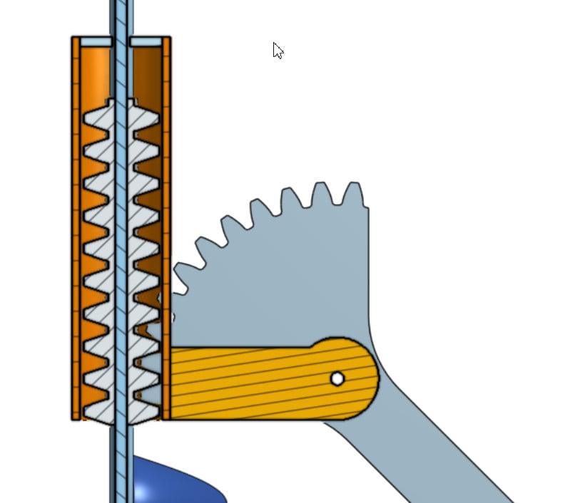
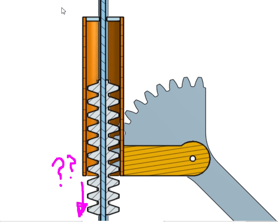
I'm trying to implement a rack and pinion mate which should be pretty easy - but when I select the slider and the rotational mate my slider part is "jumping" around 40mm causing the initial aligment to be off. When I select the slider mate it is bringing up a linear dimension from some origin but editing that also appears to mess up my rotational mate. I can't find any documentation on these additional dimensions. Any clue on what i'm doing wrong?
Before:


After I select the slider and the rotational mate


I'm trying to implement a rack and pinion mate which should be pretty easy - but when I select the slider and the rotational mate my slider part is "jumping" around 40mm causing the initial aligment to be off. When I select the slider mate it is bringing up a linear dimension from some origin but editing that also appears to mess up my rotational mate. I can't find any documentation on these additional dimensions. Any clue on what i'm doing wrong?
Before:

After I select the slider and the rotational mate

0
Comments
What you need to do is right click on the mate and select "reset", it will return the parts to their zero position, and from here you need to edit the mate connectors so the teeth mesh properly.
This thread might help explain it. I think that it's the same problem