Welcome to the Onshape forum! Ask questions and join in the discussions about everything Onshape.
First time visiting? Here are some places to start:- Looking for a certain topic? Check out the categories filter or use Search (upper right).
- Need support? Ask a question to our Community Support category.
- Please submit support tickets for bugs but you can request improvements in the Product Feedback category.
- Be respectful, on topic and if you see a problem, Flag it.
If you would like to contact our Community Manager personally, feel free to send a private message or an email.
Drill Depth Bug
 Curt_Welch
Member, csevp Posts: 42 ✭✭
in CAM Studio
I ran into an odd bug. The drill op depth gets confused, and calculates the drill op depth wrong.
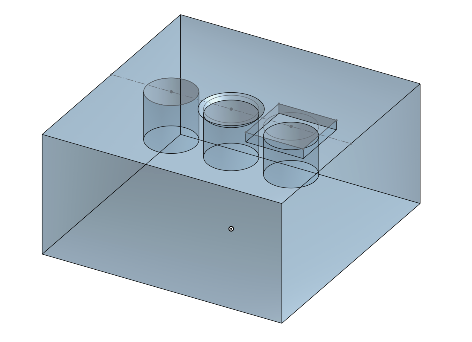
For this test block:

All the holes are 10mm deep (from the top of the part). When I try to drill to the bottom of all three, the first depth is correct, but the second and third are wrong.
The chamfer is 1mm, and the pocket is 2mm.
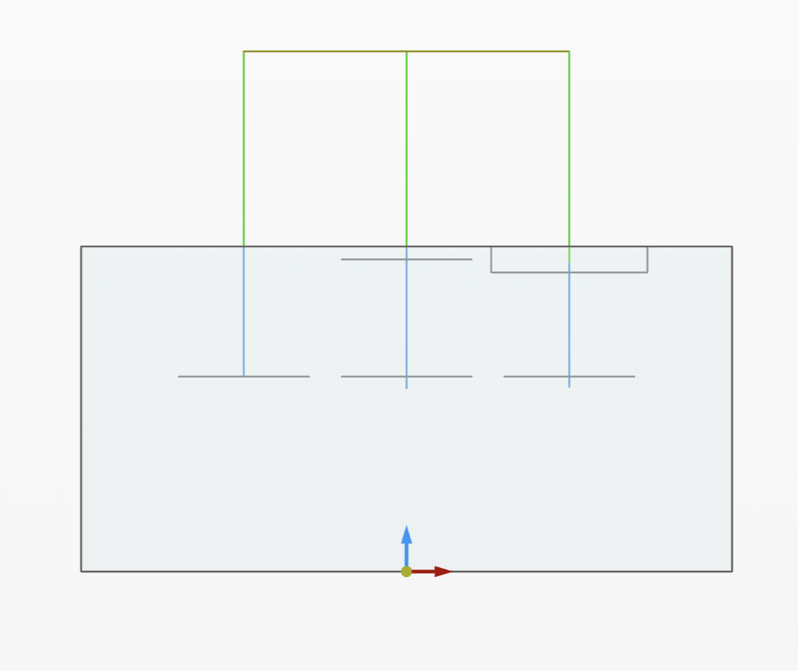
A side view of the drilling op that drills all three shows the second and third deeper than they should be:

The Gcode shows:
For this test block:

All the holes are 10mm deep (from the top of the part). When I try to drill to the bottom of all three, the first depth is correct, but the second and third are wrong.
The chamfer is 1mm, and the pocket is 2mm.
A side view of the drilling op that drills all three shows the second and third deeper than they should be:

The Gcode shows:
N8 Z10.
N9 G98 G81 X-12.5 Y-0.0 Z-10.0 R5.0 F1500.00
N10 G80
N11 Z15.
N12 X0.
N13 Z9.9
N14 G98 G81 X0.0 Y-0.0 Z-10.9 R4.9 F1500.00
N15 G80
N16 Z15.
N17 X12.5
N18 Z8.8
N19 G98 G81 X12.5 Y0.0 Z-10.8 R3.8 F1500.00
The first hole is going to the correct Z-10 (I have part zero at the top of the part), The second goes to Z-10.9, and the third goes to Z-10.8. Where on earth did it come up with .9 and .8? Also, notice the move to the start height, which is a correct value of Z10 for the first, is the odd Z9.9 in the second and Z8.8 in the third.
I found this because I was trying to use a 45° chamfer mill to do a spot drill of the hole and form a chamfer at the same time. I couldn't make it drill the depth correctly, no matter what value I was putting in.
If I'm doing something wrong in the CAM settings I don't understand what it is.
John would you like me to share this document with you? Let me know if I can help.
0
Comments
On the first hole, which doesn't have a chamfer, the hole is 10 mm deep and starts at the top of the part. The G54 Z 0 axis is the top of the part in the setup. So the first op makes a move to Z15 (the clearance height -- sorry I didn't copy and past that code above), then a move to Z10 (the feed height) and then drills to Z-10. All as expected. All good.
The next hole, the chamfer is 1mm deep.. The hole is 10 mm deep from the top of the part. The cylinder selected to define the operation is precisely 9 mm long.
But what it produces is a move to Z15 (clearance -- all fine), then drops to Z9.9 as the feed height??? Why 9.9mm? The hole that defines it is 9mm long, not 9.9. The hole is 1 mm below zero. So the feed height is 10.9mm above the start of the cylinder that defined the hole to drill and 9.9mm above the top stock. Where the heck did it get this number? Then it drills down to Z-10.9. So the depth of the dill (from feed height to hole bottom) is an odd 20.8mm move down.
Then in the third hole, the hole top is 2 mm below the stock top, and ends 10mm below the stock top. So it's an 8mm cylinder selected as the definition of the drill op.
But the g code does a feed height of 8.8mm, which is 10.8 mm above the true start of the hole. But then drills to Z-10.8. So it's drilling 17.6mm deep. Again, this is basically a random number. But it should have started the feed at 8 and ended at -10.
So a 1mm offset of the hole top created a .1 error in the feed height. And a 2mm offset in the hole top created a .2mm offset. This feels like it's an off-by-10 factor in the code. I'm wondering if any hole that doesn't start at the stock top has this error. Let me try a different test that I think might also show the error.
So, it took me all morning to figure out what triggered the bug. Most holes drill correctly, so I was confused as to why the different things I tried didn't trigger the bug. But I think I understand it now. Maybe. Maybe not,
It's all about how the body is defined in OnShape. So here's an example of a bug in a simple block with a simple hole.
The block is 20mm cubed with a 10 mm diameter hole 10 mm deep in the top. Yet it drills the hole to 11 mm deep!
The part zero is set to the top center of the hole in this Gcode:
So, the reason the bug happens on this simple part seems to be triggered by how I created it in CAD. I extruded a 20x20x100 mm tall block. Extrude a 90mm hole into the top, then cut off the top 80mm of the block, leaving the simple cube you see above.
When the hole is modified after it is made (with the extrude-remove in this example or with a chamfer, for example), the CAM gets the drill path wrong. It's only off by a small amount (1mm in this example) and .1 and .2 in my other two examples), but if the hole is modified in CAD after it is defined, it seems to trigger this depth bug, even if the resulting shape is simple, as in this example.
So, this is not just a problem caused by holes with chamfers and counterbores. It's an odd bug that can happen in multiple cases that don't look like they would be problems.
To try and understand this issue better, I just paused while writing this, and modified the above test. Instead of using a 100mm block, I made it a 1000mm block with a longer hole and which I then trimmed down to the same, resulting 20x20x20 shape. And oddly, when I tried to make the bug worse, it made the bug go away! The drill depth was correct in this other version. I really don't understand what triggers the bug. Or why it's correct in my second test?
---
The "custom level" you talked about above I've left at zero so far. I couldn't figure out what it was controlling when I looked at it and played a little. But if it's the start depth maybe it can help keep this bug away? I'll play with it.
Adjusting the depth is what I was trying to do when I first saw this bug. But for the life of me I couldn't figure out how much to adjust the depth. Thre was nothing I could do in the CAM to figure out how much this bug had added to the hole. My 1mm chamfer caused the hold to be .1mm too deep. But without reading the g-code, I couldn't see that. RTeading G-code and finding a bug value to offset ihn your CAM is not a very workable "workaround".
My workaround will be to remove the chamfers from the model and only use simple holes. I hope that will allow me to get the results I was looking for. I've been dictated for the better part of 2 days trying to understand this bug.
But no, this is not just a limitation, it's a very odd and obscure bug. But maybe, if the drill op software gets a big rewrite anyway, the bug will go away with the rewrite? But if it's not going to get a rewrite, I would have someone hunt this down and figure out why it's getting the depth wrong in these examples.
I recreated this example and made a drilling operation. The posted code looks correct in my example. Can you share the document with me so I can take a closer look?
Hole is 10mm deep
The bug vanished from the document that I had the 100mm cut down to 20mm. I had made some changes I thought were insignificant then the bug went away. So I removed the changes I made and the bug didn't come back. Even trying to go back in the history, I couldn't get the bug to return.
But I had two other documents that showed the bug, and when I opened them, they still had the bug.
But now that I am trying to find something to share with you, CAM studio hangs with a rotating circle saying "loading" and doesn't seem to want to open. Some other CAM Studios can open, and I can create a new empty CAM Studio. Maybe an upgrade is happening? I'll keep checking, and if it becomes stable and I can share an example of the bug with you, I will.
But I was able to recreate the issue, in a Document called "Drill Bug" which I have shared with you John.
The hole is 10mm deep but it produces G-code that drills to 11mm deep. Most other times I've seen the bug it was some random small number < 1. Like ,544mm too deep. Odd that this one is exactly 1mm off. I've never seen the error drill more than 1mm off from what would be correct so it's a small bug.
The good thing is that the tool path is visualized to show the error, so it's not hidden. The error has always been on the "too deep" side, so the only problem it would create in real life is drilling out the bottom of a tight blind hole or drilling into a fixture, etc. But something odd is randomly happening that should not be with the depth calculation.
Note that the start height is also always off. But while the drill is too deep, the start height is too high. So if the drill stop point is .1 too deep, the start height is .1 too high. So the total drill path is 2x longer than it should be,
Using the custom depth doesn't make the bug go away, nor does using the custom level value.