Welcome to the Onshape forum! Ask questions and join in the discussions about everything Onshape.
First time visiting? Here are some places to start:- Looking for a certain topic? Check out the categories filter or use Search (upper right).
- Need support? Ask a question to our Community Support category.
- Please submit support tickets for bugs but you can request improvements in the Product Feedback category.
- Be respectful, on topic and if you see a problem, Flag it.
If you would like to contact our Community Manager personally, feel free to send a private message or an email.
Face blends not printing correctly in 3d prints
 ilana_kaye
Member Posts: 6 ✭
in Drawings
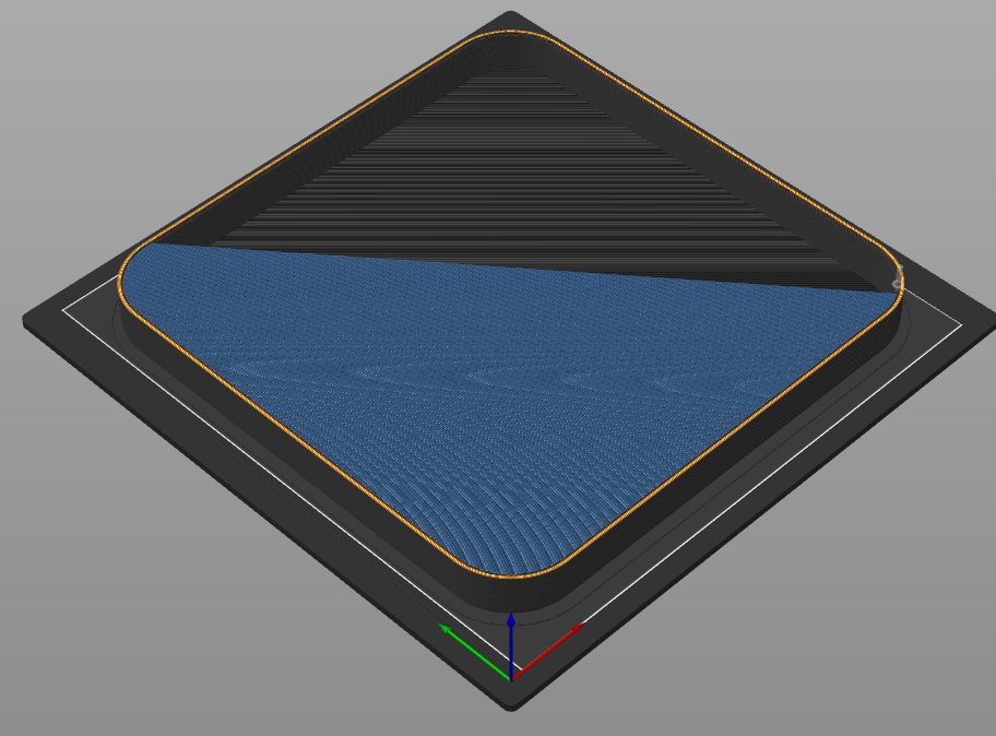
I have designed a piece that used face blends to connect the rim with the base of a stackable tray but when I go to slice the file, it tries to fill in the entire tray from the blend up.
This is my file: https://cad.onshape.com/documents/c612f858021f6684e9e181bb/w/691d60ddd5d7d9122a174713/e/f9dcd2cd5e88d18614ce9905
And this. is what it looks like in the slicer at the layer the face blend starts at

This is my file: https://cad.onshape.com/documents/c612f858021f6684e9e181bb/w/691d60ddd5d7d9122a174713/e/f9dcd2cd5e88d18614ce9905
And this. is what it looks like in the slicer at the layer the face blend starts at

0
Comments
Face blends are surfaces which don't print since they have zero thickness. They need to fill as solid by some means. They also do nothing for the Boolean of solids.
Attached is one idea to accomplish what your after.
https://cad.onshape.com/documents/2d27ee37ee7bae74baf92546/w/e913b39f99f33b6568c9386a/e/1cd33e6bf0a14ee943b6d102
but on Sketch 4 I was only able to select "face of sketch 4". You have "faces of sketch 4". Can you tell me why couldn't select faces?
In sketch 4 not the use of the "use" command so that the so that the curves will update when other geometry changes. Blue cubes in sketch 4.
https://cad.onshape.com/documents/e9ff561821a93fd4eae3737e/w/96b86fd8aadcf5fb88182b17/e/e932dc4ed2da6474db403da6