Welcome to the Onshape forum! Ask questions and join in the discussions about everything Onshape.

First time visiting? Here are some places to start:
  1. Looking for a certain topic? Check out the categories filter or use Search (upper right).
  2. Need support? Ask a question to our Community Support category.
  3. Please submit support tickets for bugs but you can request improvements in the Product Feedback category.
  4. Be respectful, on topic and if you see a problem, Flag it.

If you would like to contact our Community Manager personally, feel free to send a private message or an email.

Debossed text on curved surface

henrik_viklundhenrik_viklund Member Posts: 5
Hello!
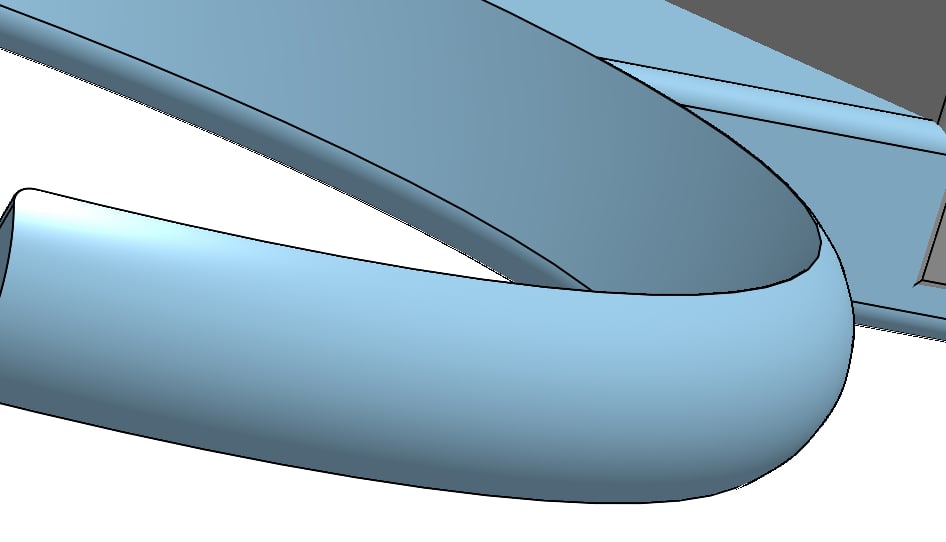
I need help creating a debossed text on a curved surface. Since it is not cylindrical, I cannot use the function wrapped and I can’t find any projection tool. Anyone with an idea?

Comments

  • glen_dewsburyglen_dewsbury Member Posts: 782 ✭✭✭✭
    Hear us a sample based on earlier comments from 'improvement's to Onshape Jan 12'.
    Hope it helps.
    https://cad.onshape.com/documents/369daf3ed32938c733916414/w/cf291417ed98c5293637724f/e/bcb0b19d264de5fd6a86fb98
  • henrik_viklundhenrik_viklund Member Posts: 5
    Thanks, but I can’t use wrap on a non-cylindric surface. I guess I’ll just have to stick to shaper3d.
  • martin_kopplowmartin_kopplow Member Posts: 505 PRO
    You could use a two-step process: First create a cylinder face close to your surface, then wrap text onto that and finally project wrapped text onto your target face.
  • henrik_viklundhenrik_viklund Member Posts: 5
    Thanks! How do I project the wrapped text?
  • romeograhamromeograham Member, csevp Posts: 676 PRO
    You can use the Surface Text custom FeatureScript to help you (here's the original from @dave_cowden : https://cad.onshape.com/documents/cfec40e2b66bb4ddb2f3414b/v/3f1bcca2812d650a51c9960d/e/c8e6602fb08acac97a10a38e)
    This document shows a couple of examples on two different types of faces: revolved and swept along a spline or curve.


    Stay with Onshape!


  • Glenn_BabeckiGlenn_Babecki Member Posts: 30 EDU

    I am working on a project where I want to deboss or engrave the text on a flat circular surface.  I can create raised text but I can't create debossed or engraved text.  I can't see any obvious error in my configuration of the Surface Text command.


    I loaded Dave Cowden's Surface Text FeatureScript from the link provided in several forum discussions on the topic.  The version I pulled is shown below shows up as a beta version.
    I copied your test curve text example and noticed two versions in your example document.

    What are the two versions "Surface Text (NG)" and "Surface Text" and I assume it's the "Surface Text" is the one used in your example.  When I go to the respective linked documents for your version of the FS I see you created a "thin wrapper" around Dave's original script.  However, a cursory examination of the at the top of both FS instances in you example document appear to be the same version.


    I'm wondering if you did something to fix a bug in Dave's original script.  I'm going to replace Dave's FS with yours to see if it fixes my problem and get back with my findings, but I would like to understand more about what you did.

    Thanks,
    Glenn 
  • S1monS1mon Member Posts: 2,982 PRO
    You may want to try this newer Featurescript, "Text Path".

  • Glenn_BabeckiGlenn_Babecki Member Posts: 30 EDU
    Thanks for the pointer to this other script.  I was away for a week plus and recently got back to this issue.  I quickly tried it and I'm not sure if it's going to work.  First of all the lack of kerning makes the letter spacing a little weird visually.  I followed the suggested steps to first create the text layout then perform a Boolean to subtract the characters from the surface.  However, it is hard to tell if the characters actually appear engraved as illustrated in the examples in the link provided.  I have to think about this a bit more.
  • jnewth_onshapejnewth_onshape Member, Onshape Employees Posts: 87
    @S1mon
    Another vote for kerning, I see.

    @Glenn_Babecki
    Can you share a document with us? Your use case is exactly what Text path is for, so Im wondering why you aren't getting the result you want. Apart from the kerning (not yet implemented) you should be able to do either of these workflows:
    1. create sketches with Text path, then do your usual extrude-remove operation to cut that text in to the subtrate or
    2. create solids (make sure they extrude in the correct direction, in to the part) then do a boolean subtraction to remove them from the substrate.

  • S1monS1mon Member Posts: 2,982 PRO

    Again, there might be less need for a kerning option if the fonts had better hinting or control over letter-to-letter spacing. The only need I've had for kerning was to fix what looked like egregious mistakes, not to do something special or unusual. If I'm really dialing in kerning to create a logo or something like that, I would do it in Illustrator. 
  • jnewth_onshapejnewth_onshape Member, Onshape Employees Posts: 87
    @S1mon yeah i see your point. Ideally kerning would take care of itself, but given how Text path creates distinct sketches per letter grouping, I need to be able to tweak spacing manually.
  • Glenn_BabeckiGlenn_Babecki Member Posts: 30 EDU

    I got around playing with this some more.

    I tried a "different version" of the Surface Text Featurescript (V9 vs. Beta 2.1.7) for what it was worth, but it didn't seem to make a difference.  I don't know why it wasn't working for me because I've made copies of related test documents with both versions and "engraving" or cut out appears to work in those examples.  Perhaps I should try importing my Parts Studio object into one of those documents and see if it behaves appropriately.

    I noticed that the Text Path Featurescript had a new version so I did an update.  I'm not sure that that really did anything because I turned on Translucent Shading and zoomed in to get a better look at the text features, and I think it was really "engraving" all along; it's just not that obvious when you look at the part, I think because of the graphics surrounding the letters.  The kerning is still problematic for me so not clear if I have the resources to fix that with Text Path.

    Here is a shared link to the working test bed document which includes both a Text Path and Surface Text options. If you try to select the Cut Out option for the Surface Text version you will encounter a "did not regenerate properly" error.


    Please let me know if you find something that I'm doing incorrectly.

    Thanks,
    Glenn


  • jnewth_onshapejnewth_onshape Member, Onshape Employees Posts: 87
    Hi @Glenn_Babecki
    It can be difficult when creating solids, because they are created "beneath" the surface of the substrate part. One visual check I rely on is to look at the part list before and after. Text path typically creates quite a few parts:


    I'll add some kerning-like control in as the next feature enhancement. 
  • Glenn_BabeckiGlenn_Babecki Member Posts: 30 EDU
    Thanks for looking at my construction.  I have a couple of follow up questions before proceeding with either script.

    I realize Dave Cowden's Surface Text script is not your creation, but I was wondering if you looked at that Part Studio option and had any thoughts about what is happening when I attempt to invoke the "Cut Out" option.  Working examples (up to the point where the script has stopped working for people using it) clearly illustrate the engraved lettering.  I reached out to Dave in another forum thread but haven't heard back from him as of yet.  I haven't gotten into FeatureScripts yet, but I'm thinking of making an attempt to debug what's going on.

    On a whim, I tried to copy my part into the Surface Text example document, but the cut-out error still occurred.  After the fact I thought perhaps I had some residual version thing going on when I copied my part into the working example document, so perhaps I should try the experiment by creating the part from scratch to ensure no version contamination.

    As for the Text Path FeatureScript, it's not visually clear if the Boolean Subtract or Extrude Remove steps are actually "removing" material because of the image created by Text Path itself.  I can see the effect of tweaking depth dimensions with a Boolean or Extrude operation, but it leaves one with an uneasy feeling.  I will export as an STL file to examine what the 3D print slicer sees for additional confirmation of what's going on in the part surface.

    Out of curiosity, do you have any ETA for adding kerning control to the Text Path script?  Inquiring minds would like to know. :-)

    Thanks for your input on my dilemma.

    Regards,
    Glenn

  • jnewthjnewth Member, OS Professional Posts: 19 PRO
    Hi @Glenn_Babecki
    I think the best thing to do would be to "Hide" all the sketches produced by the Text path feature. There are a couple ways to do this. One is by hiding the Text path feature itself:

    Another is to click on the ">" to the left of the Text path feature to view all the sketches and then hide them, either all or individually, depending on what you need:


    Another thing to try is: After you create your cutouts with the boolean or extrude approaches, you can select the subtrate part (the part you are cutting in to) and Right-click "Hide other parts". This will leave you with _just_ the part of interest visible (well, that and sketches) so you should be able to see the effect of the cutout from that point. 

    In this screenshot, I just want to look at the "Top Arm" part (where ive cut my text) and want to hide the Upper and Middle parts. Assuming Ive hidden all sketches, I should be able to see just the part Im interested in.

    Here Ive gone in to your shared link and done exactly the above. I first hid all the sketches by clicking the eyeball next to the text path feature itself, then I right clicked on Part 1 and selected "Hide other parts":


    Now it's pretty easy to visualize.

    Was playing with kerning over the weekend. I've got a few ideas but it might take me a couple weeks. I'll post when it's ready. 
  • Glenn_BabeckiGlenn_Babecki Member Posts: 30 EDU
    D'oh; I totally forgot about Hiding Sketches and Parts to reveal the resulting detail.

    I exported an STL file to visualize the part for 3D printing, but weirdly(?) I don't see the engraved letters in the slicer.  Is there something regarding the letter dimensions or resolution that would prohibit the engraved letters from appearing in the slicer view?  The embossed or raised letter version appears in the slicer as expected.

    I'll be interested trying the kerning once you get that working.

    Regards,
    Glenn

  • Glenn_BabeckiGlenn_Babecki Member Posts: 30 EDU
    UPDATE:
    I was tinkering further with construction behavior and got the lettering to appear in the 3D printer slicer application.  I don't recall exactly what I did but I suspect it was the reworking the faces/sketch selections in the Extrude/Boolean operations.  I know I should have kept better notes.

    On a good note, I found an available Text Path font and weight combination what appears to have acceptable kerning while mimicking the font I'm trying to replicate.  This should hold me over while I figure out the best way to 3D print the part.  I suspect that I'll have to section the part for printing without a lot of crazy supports that will mess up the surfaces and employ some cyanoacrylate glue to assemble the sections.

    Glenn

  • jnewth_onshapejnewth_onshape Member, Onshape Employees Posts: 87
    @Glenn_Babecki
    If you can, avoid STL. It is ancient and terrible, like the Balrog.

    If you can, use STEP or parasolid. Most slicers support these and they are better for representing solid geometry. 
  • Glenn_BabeckiGlenn_Babecki Member Posts: 30 EDU
    Good to know.  I didn't realize the slicer could import other file formats.  I'm using the most recent UltiMaker Cura slicer so I'll check allowable formats.

    I only recently got into 3D printing, but I haven't done anything in several months.  I need to buckle down and understand all the printing controls and various material behaviors anyway, so this is a good excuse to dig into the file format issue as well.

    I've using Onshape sporadically for a while, but only scratched the surface of CAD design with Onshape as mechanical design is an adjunct to my mainstream electronics and embedded software development.  I have no delusions that I have a lot to learn about Onshape and mechanical design.

    Thanks for all your help.

Sign In or Register to comment.