Welcome to the Onshape forum! Ask questions and join in the discussions about everything Onshape.
First time visiting? Here are some places to start:- Looking for a certain topic? Check out the categories filter or use Search (upper right).
- Need support? Ask a question to our Community Support category.
- Please submit support tickets for bugs but you can request improvements in the Product Feedback category.
- Be respectful, on topic and if you see a problem, Flag it.
If you would like to contact our Community Manager personally, feel free to send a private message or an email.
How can I extrude surfaces between my sketch lines?
 Aero_Modeler
Member Posts: 2 EDU
Hi!
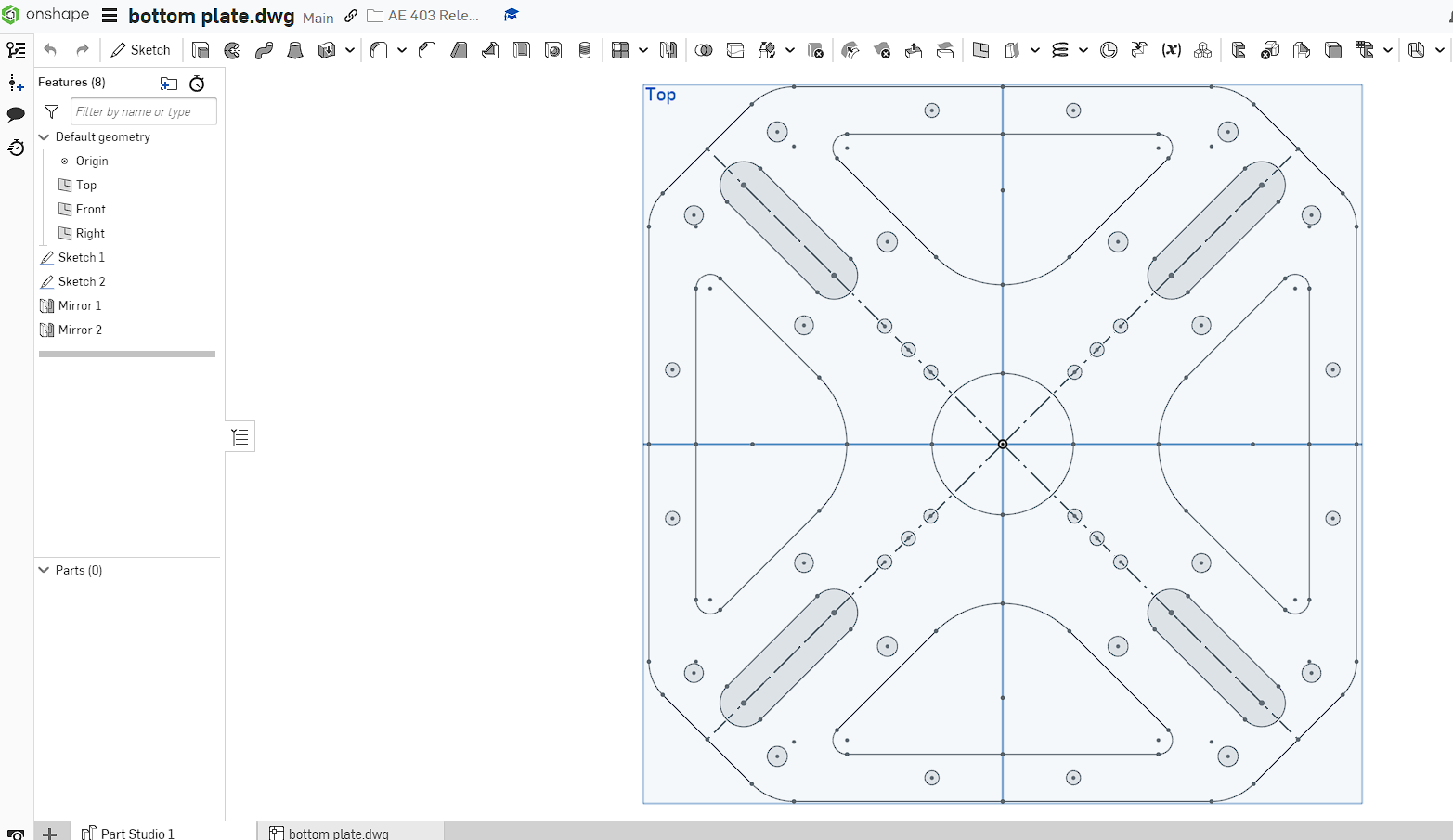
I've created a sketch of a top plate for a drone off of an existing design. However, when I attempted to extrude it into a part it was only extruding the sketch lines and the places I have circles and slots. Is there any way to essentially flip what is being extruded so that it is everything between the sketched lines, circles, and slots?

I've created a sketch of a top plate for a drone off of an existing design. However, when I attempted to extrude it into a part it was only extruding the sketch lines and the places I have circles and slots. Is there any way to essentially flip what is being extruded so that it is everything between the sketched lines, circles, and slots?

Tagged:
0
Best Answer
-
 matthew_stacy
Member Posts: 489 PRO
@Aero_Modeler, I would strongly encourage you to sketch less. A large complicated "masterpiece" sketch like you are working on can be challenging to troubleshoot and fix, like trying to find and close gaps as you are doing now. Follow this example to see how you might break the model into small, bite-size pieces. Step through the feature tree line by line to follow the progression.I started with a single wedge comprising only an eighth of the final part. The sketch is just a 45 degree triangle. Then make another sketch defining just the slot. Then mirror that part, resulting in a quarter wedge of the final part. When ever possible pattern (or mirror) PARTS, or if necessary FEATURES. Mirroring or patterning sketch entities is a last resort, and should be avoided whenever possible.It can also be advantageous to create chamfers and fillets as parametric feature rather than sketching them in.In summary, sketch much less of the part and then mirror and/or pattern the part itself. Make more, simple sketches that focus on a very small number of features. Don't sketch geometry that can be more readily created with model features. It's called parametric-feature-based CAD for a reason. There are some great tutorials on these topics in the Onshape Learning Center.


 0
0
Answers
I largely agree with you, but there are a few exceptions to doing a lot of mirroring of features (as opposed to sketch elements) like this:
Simon Gatrall | Product Development, Engineering, Design, Onshape | Ex- IDEO, PCH, Unagi, Carbon | LinkedIn