Welcome to the Onshape forum! Ask questions and join in the discussions about everything Onshape.

First time visiting? Here are some places to start:
  1. Looking for a certain topic? Check out the categories filter or use Search (upper right).
  2. Need support? Ask a question to our Community Support category.
  3. Please submit support tickets for bugs but you can request improvements in the Product Feedback category.
  4. Be respectful, on topic and if you see a problem, Flag it.

If you would like to contact our Community Manager personally, feel free to send a private message or an email.

I have a tileable part that I want to test how it fits together. How do I do that?

kyle_bryson580kyle_bryson580 Member Posts: 12
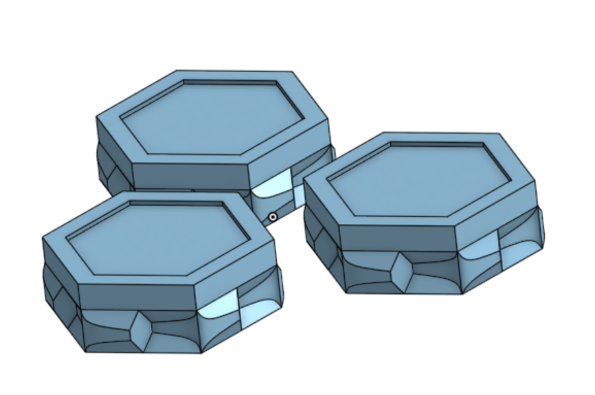
The part is hexagonal, and I want to test how it will connect together, but I don't know how to do that. I need to have some way of making sure the parts don't intersect. Does anyone know of a way I can do this? Thanks.
Answers

  • Matt_ShieldsMatt_Shields Member Posts: 373 EDU
  • kyle_bryson580kyle_bryson580 Member Posts: 12
    That is not what I want. I want to be able to test how they fit together, as in how connecting them will feel. I need to test how the third will fit in as I am connecting them, and I need some way of detecting when they collide, and stopping them from going further.
  • dirk_van_der_vaartdirk_van_der_vaart Member Posts: 547 ✭✭✭
    One thing is sure, If it fit,s exactly it is not going to fit.
    The first two maybe, but the third never.
    Some faces need to have an offset.
    And how do you want to produce these part,s, ??
  • kyle_bryson580kyle_bryson580 Member Posts: 12
    edited February 6
    I'm planning to 3D print them. From what I've researched, the average 3D printer should be able to print it all as one piece, overhangs and all, because the angle is much less than 45 degrees (which would have the filament half on and half off the previous layer). As for them fitting together, the first two should fit, unless I need to slightly shrink the protruding portion, or change the shape of the intersect, and the third should be able to rotate in. They won't be able to fit in super easily, but because of the way it isn't just a slab protruding out, it should be able to snap together. As you can see by this cross section, you should be able to rotate it in place. I just want to be able to test that without 3D printing, if possible.
  • dirk_van_der_vaartdirk_van_der_vaart Member Posts: 547 ✭✭✭
    It also depends of the roughnes of the surface,s after printing.
    Move faces ot the marked faces a bit out and you have control of the process

  • kyle_bryson580kyle_bryson580 Member Posts: 12
    Ok... Do you know how I could test whether it would fit together without 3D printing it first?
  • dirk_van_der_vaartdirk_van_der_vaart Member Posts: 547 ✭✭✭
    No I don't know, it mostly depend's of the quality of your printer and how big the parts are.
    You have not shared your document so I cannot know.

    And as I said before, if something fit,s exacly it doesn,t fit.
  • nick_papageorge073nick_papageorge073 Member, csevp Posts: 783 PRO
    Make an assembly. Do an interference check on the assembly. It will show if/where the parts collide. When you build the assembly, orient the mates in the direction you intend to assemble it in real life. If you see a collision in the interference detection, go and edit that assembly mate to push the part out a little bit. Then run the interference check again and see what it did.

    All that said, to be honest, printing is so fast and easy, I'd just print it. In general it's best to get designs to printers asap, with the printer next to your cad computer, while you keep working on improving the design. Keep the prints short and fast, cutting the parts much smaller to just test a specific area of interest, so the print just takes 15 min.
  • nick_papageorge073nick_papageorge073 Member, csevp Posts: 783 PRO
    edited February 8
    The assembly really is your tool, I don't know why you don't want to make one. Once in the assembly you can also take cross sections from many different angles. Interfering areas will show red. That's very simple and fast to do. I'd actually do that before what I wrote in my prior post.

    I'd still print asap though. (now). Unless you don't own a printer and have to pay someone else. Then, its a different situation.
  • martin_kopplowmartin_kopplow Member Posts: 455 PRO
    In my experience, with all kind of printed parts, you need to create an minus-offset on all surfaces meant to fit together. How much offset is needed depends on the printing process, material, post-processing, and so on: You will inevitably get a certain amount of roughness depth and that can only be determined by analysing printed parts. 
    Example: For the quick and dirty sample part process using my desktop FDM printer, it is usually 0,15mm per side for parts as they fall out of the machine, whereas it's 0,08 mm per side for the parts my preferred printing service delivers. For that reason, I usually keep the roughness depth offset as a separate variable feature.
    If you are looking for undercuts, and you know the direction of assemly, you may also find the Isocline Tool useful: 


  • michael3424michael3424 Member Posts: 687 ✭✭✭✭
    There are calibration test parts that will give an idea on how much offset is required for closely-fit parts to actually fit together in practice.  For example:

    https://www.makersmuse.com/clearance-and-tolerance-3d-printer-gauge

  • kyle_bryson580kyle_bryson580 Member Posts: 12
    It is in an assembly. It fits. I need to make sure it doesn't intersect while putting it in. I need something like collision detection so that as I'm moving the parts around in the assembly, objects don't go through each other.
  • kyle_bryson580kyle_bryson580 Member Posts: 12
    I do not own a printer, though I have a friend who does. I just would prefer to test without printing so that I don't take up too much of their time until I am ready to do the full print. If that isn't possible, then oh well.
  • kyle_bryson580kyle_bryson580 Member Posts: 12
    So the only way to test is to print it out?
  • kyle_bryson580kyle_bryson580 Member Posts: 12
    Alright, I'll keep that in mind, but an interference check won't work, because I need to make sure it doesn't intersect while inserting it. If you can do that in what you explained, then I am unfortunately needing a more elaborate explanation, because I have found nothing that can help me with this. If I have to print, that's alright, but if not, great! The size of these is ~2.5 centimeters in diameter (a little more due to the protrusions, but it evens out with the indents).
  • nick_papageorge073nick_papageorge073 Member, csevp Posts: 783 PRO
    Alright, I'll keep that in mind, but an interference check won't work, because I need to make sure it doesn't intersect while inserting it. If you can do that in what you explained, then I am unfortunately needing a more elaborate explanation, because I have found nothing that can help me with this. If I have to print, that's alright, but if not, great! The size of these is ~2.5 centimeters in diameter (a little more due to the protrusions, but it evens out with the indents).
    Make your assembly with the parts in the position/s they will be when inserting them in real life. With the parts at those positions, run the interference detection in the analysis tools at the bottom right corner of the assembly window.
  • kyle_bryson580kyle_bryson580 Member Posts: 12
    I need to test the intersection during the entire process. I can't just do that, because that's one snapshot, not the entire time, and it won't be accurate to real life, because I won't be moving it in a realistic way. I need smooth, continuous collision detection, that prevents collision, for example, like objects colliding in a game. Not like whatever you are failing to explain to me in a way I can understand.
  • matthew_stacymatthew_stacy Member Posts: 487 PRO
    The part is hexagonal, and I want to test how it will connect together, but I don't know how to do that. I need to have some way of making sure the parts don't intersect. Does anyone know of a way I can do this? Thanks.
    @kyle_bryson580, unless you're willing to invest in a high-dollar CAD system (tens of thousands of dollars) you are not likely to get DYNAMIC COLLISION DETECTION, that will allow you to simulate a realistic fit-up process.  What you can do, is create an assembly of multiple tiles in one or more static positions (partially installed, fully installed, etc.) and evaluate INTERFERENCE (meaning "overlap") at each step.

    Here is a simplistic example to illustrate the concept.  Click that link to open the document and then save a copy to that you can fully interrogate the Part and Assembly studios.

    The first step is to create the "tile".  Mine is simply a rectangular block, with mate connectors placed on two opposing sides for subsequent placement in an ASSEMBLY.  I would encourage you to work through a few simplified model and peruse the Onshape Learning Center for tutorials on sketching, solid modeling, and assemblies.  The content of those videos is extremely high quality.

    Notice that the mortise (female interconnect feature) is wider that the tenon (male interconnect feature) providing exaggerated CLEARANCE.  However, I intentionally made the mortise shorter than the tenon to illustrate INTERFERENCE when we assemble two tiles together.

    Here is a screenshot showing the completed tile with both of the interconnect features and "mate connectors".

    Note that thus far we have been in the PART STUDIO environment.  Now we are going to open an ASSEMBLY STUDIO and insert the PART named "Tile" into an assembly, centered on the origin, and FIXED so that it cannot move in any direction (zero degrees of freedom, no rotation, no translation).

    Notice that I already placed a second tile, but I have temporarily hidden it from view.  If we unhide the second tile it looks like this:

    The 1st tile is FIXED.  That is the foundation.  The 2nd tile is FASTENED to the 1st tile, mated face to face.  We are interested in assessing whether or not the mortise and tenon interfere with one another.  You can easily see the interference in this view because it is greatly exaggerated and there are no other features blocking our view.  Most designs will be more complex.

    Now select both parts, "Tile 1" and "Tile 2", right click on one of them and select CHECK INTERFERENCE:


    Notice that Onshape highlights the zone of interference in red, making in much easier to detect.  Typically interference might be on the order of tenths of a millimeter (or thousandths of an inch) and easily missed without a CAD platform like Onshape.


    Section views can also be helpful to reveal zones of interference, but that's another story for another day.  Be aware that 3D printers have limited resolution and absolute accuracy is less than could typically be achieved in a machining process.  As others have already stated in this conversation, calibration will be required based on the results of test parts (adjusting clearance/interference) to get that perfect, Goldy-Locks, just-right fit.

    Does any of this help?
  • kyle_bryson580kyle_bryson580 Member Posts: 12
    I guess I'll just have to 3D print. Thanks for the help anyway!
Sign In or Register to comment.