Welcome to the Onshape forum! Ask questions and join in the discussions about everything Onshape.
First time visiting? Here are some places to start:- Looking for a certain topic? Check out the categories filter or use Search (upper right).
- Need support? Ask a question to our Community Support category.
- Please submit support tickets for bugs but you can request improvements in the Product Feedback category.
- Be respectful, on topic and if you see a problem, Flag it.
If you would like to contact our Community Manager personally, feel free to send a private message or an email.
simplifying/removing excess vertices from imported DXF files
 chris_shelton096
Member Posts: 6 ✭
So Im trying to figure out the best/fastest way to essentially clean up DXF files for laser cutting.
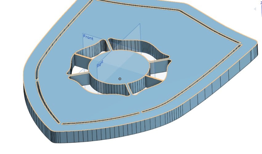
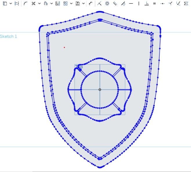
I usually have to work off an image or PDF to create a DXF for plasma/laser cutting and I'm having a hard time where when I import the DXF into onshape there's a TON of seemingly useless vertices along straight lines, more than seems necessary on some curves etc.
is there an easy way to eliminate the extra points? or am I stuck manually deleting them, or having to manually retrace the image?
heres an example.
https://cad.onshape.com/documents/d04ae981c4de9b6b849fe26b/w/4b136ea9270202e2fd3a001c/e/52019222f32d271992a7df16
The goal is smooth clean edges.
Thanks for any help


0
Comments
https://cad.onshape.com/documents/f9a79906900a96bd2f11429a/w/9d979ac335fde7624467fc0b/e/5ebb0e7e3ec445d853005acb
- Where are the DXF files coming from? Was there an option to export splines instead of poly lines?
- How clean does this need to be?
My personal inclination would be to redraw the whole thing, but that's because I'm super familiar with this kind of thing, and can make the shape as clean as possible. However, looking carefully at the data you have, it's not symmetric, or very consistent. There are weird little jogs, and fillets which look similar at first, but are not, and aren't even constant. There will be a certain amount of work to make this clean, and depending on the scale of the output or the size of any errors, all the clean up and/or errors could be swallowed by the laser kerf and/or sanding or other cleanup.Simon Gatrall | Product Development, Engineering, Design, Onshape | Ex- IDEO, PCH, Unagi, Carbon | LinkedIn
then importing to onshape to make sure everything is scaled properly and either making a step file for laser cutting off site, or using f360 to create a gcode to cut it on our arcdroid with plasma.
the original pdf i think was done by a design/print company for us to use as a template to cut the backing of a sign.
im trying to get them converted to step files for laser cutting using onshape, or gcode for our arcdroid if its something without lines too fine for plasma cutting and not too big for the machine.
outside perimeter is easy to clean up if its not super smooth but the inside lines would be an absolute PITA.
Simon Gatrall | Product Development, Engineering, Design, Onshape | Ex- IDEO, PCH, Unagi, Carbon | LinkedIn
It's not too onerous to redraw on top with simpler segments and aim for good enough approximation, but whether or not the approximation is good enough is a question for you.
Building on @glen_dewsburymodel, this took me 20 min:
https://cad.onshape.com/documents/f832e663cb0cb1a0a59d0d09/w/bdc441f241f4d32ed847ae0f/e/52b1f7a462c1b3e4b58c5793
To speed this up, I made use of near-symmetry (each petal has midline symmetry, then the flower is a 4x circular pattern of petals, and the shield details have midline symmetry). But the source image is not itself symmetric so using symmetry introduces deviations.
Here's the worst deviation I could find:
Which is a lot! Until you realize the shield is ~16" horizontally. OTOH if this emblem is intended to be symmetric, this might be an improvement!
A best fit simplification would compute a series of cubic splines to match the extant curves which (assuming your laser can smoothly interpolate along a spline path) would have the minimum number of segments AND would match the source doc's asymmetries. Couldn't finish that in my lunch break, however.
Hope it helps!