Welcome to the Onshape forum! Ask questions and join in the discussions about everything Onshape.
First time visiting? Here are some places to start:- Looking for a certain topic? Check out the categories filter or use Search (upper right).
- Need support? Ask a question to our Community Support category.
- Please submit support tickets for bugs but you can request improvements in the Product Feedback category.
- Be respectful, on topic and if you see a problem, Flag it.
If you would like to contact our Community Manager personally, feel free to send a private message or an email.
New Feature: Text path
 jnewth_onshape
Member, Onshape Employees Posts: 89
Here is my latest custom feature: Text path.
The purpose of this custom feature is to lay out characters, words, or number sequences following a geometric arrangement (clock faces, wheels, dials) or alignment.
You can watch a demo video here: https://www.loom.com/share/19705d168c314cedab26787a13961b64?sid=2e4d09f9-bae3-4f08-857d-38b7ea599fa2
You can get the feature here: https://cad.onshape.com/documents/4e187c2b2f7f4974f4e2b612/v/04e7ad76e7b3e4008b7632cc/e/8639f00c4f54af50704861a9
Some common examples (arranging numbers for a clock):

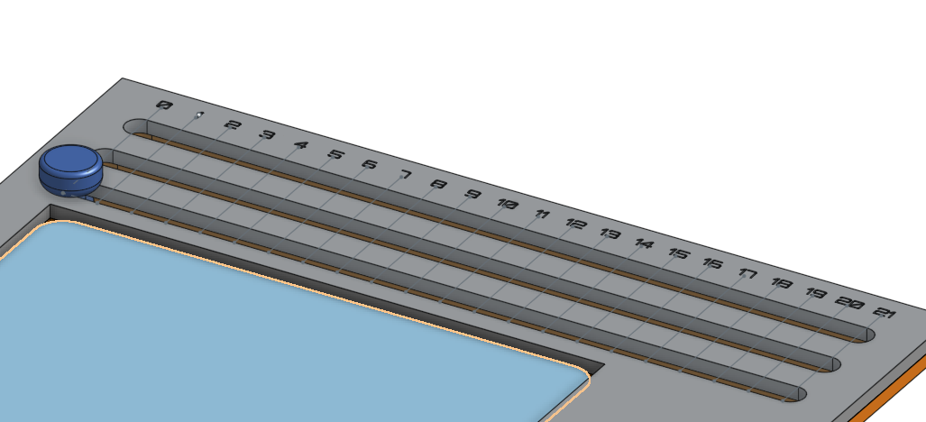
Or arranging numbers along a slider track:

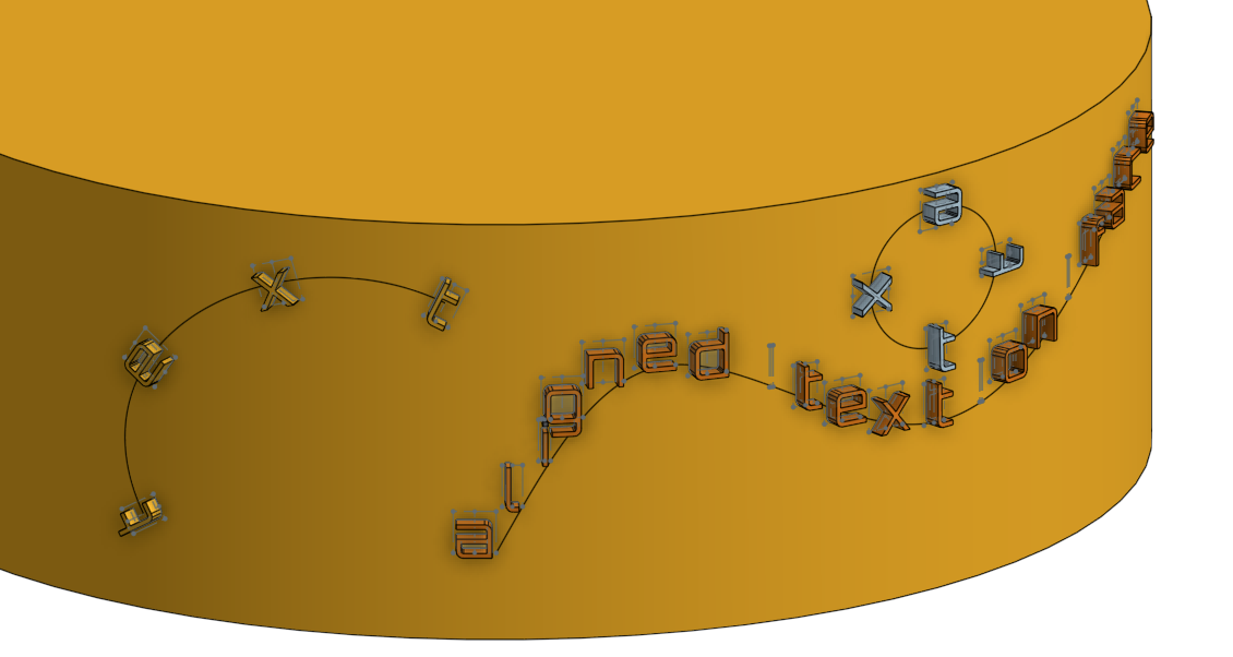
But it can work on most surfaces, even irregular ones:

Let me know what you think!
The purpose of this custom feature is to lay out characters, words, or number sequences following a geometric arrangement (clock faces, wheels, dials) or alignment.
You can watch a demo video here: https://www.loom.com/share/19705d168c314cedab26787a13961b64?sid=2e4d09f9-bae3-4f08-857d-38b7ea599fa2
You can get the feature here: https://cad.onshape.com/documents/4e187c2b2f7f4974f4e2b612/v/04e7ad76e7b3e4008b7632cc/e/8639f00c4f54af50704861a9
Some common examples (arranging numbers for a clock):

Or arranging numbers along a slider track:

But it can work on most surfaces, even irregular ones:

Let me know what you think!
8
Comments
@GWS50 Yes, Onshape's text tools are good enough for laying out one or two strings or characters, but for number sequences or geometric arrangement of different text elements, I think this is a better tool. Or at least that was the hope
Nice icon too
Learn more about the Gospel of Christ ( Here )
CADSharp - We make custom features and integrated Onshape apps! Learn How to FeatureScript Here 🔴
I have worked with surface text, with which I have some problems. I'd like to "carve" the letters 0.4 mm deep into a surface and then extrude these new surfaces again for 0.4 mm to be level with the surface again - but as seperate parts. It's for text on the first layer and non protruding text.
With Surface Text I haven't found a way to do this yet. Text will always stand out from the surface.
Is Textpath capable of "engraving" text as seperate paths? Something like that:
The Text has first been removed / carved into the body surfeace and the next step is filling the removed letters with extrusion mode "New", to get all letters as seperate parts. Thus I can use different tools in my printer (Prusa XL) to print text in different colors - smooth an not protruding.
Because text is (in my experience) sort of weird to work with, I didn't make a lot assumptions about how designers will use the text. In fact, the default Text path behavior is to not produce parts at all - just sketches:
If the user wants to create parts, they select the "Create solids" option:
From there, you can do a boolean subtraction to subtract the text from the base part, but select "Keep tools" to leave your text bodies:
And then you get what you want:
Alternatively, you could just create the Text path sketches, then re-use the sketches, once for engraving, once for extruding.
While you were typing I texperimented a little more and found the sketches. From there all has been easy ...
I know, I'll love that feature!!!
1. Created a new plane
2. Created a sketch on that plane with a simple line
3. Extruded a surface from that line into the cylinder
4. Created the path by creating an 'intersection curve' of the cylinder surface and the newly created surface (from point 3)
Whether that's the most elegant way - I doubt it, but eventually it has worked out after some desperation ...
As @eric_pesty intuited: I used a projected curve to transfer a line on to the surface:
if you open the doc containing the featurescript, go to the "examples" folder and you can see how I created all the CAD used in the photos and video.
I am pleased to announce "Release 3". Same document but make sure to get "Release 3": https://cad.onshape.com/documents/4e187c2b2f7f4974f4e2b612/v/a94c2b1949ec131c8d9eb61f/e/bbfe4eb9f6b097e2ab503d67
Note: Updating existing "Text path" features will likely change them geometrically so verify the results after updating existing features.
2. The feature has a new set of orientation controls and a new angle orientation manipulator:
3. "Text path" has been renamed to "Text" for brevity and features now auto-rename based on input.
4. Solids can be created as individual parts or a single closed composite solid.
5. UI has been simplified to group related elements.
6. Text can now place a single instance (that is, you can use this custom feature as a replacement for sketch-based text). The text will be located at the line's centerpoint by default or at a user-specified point.
Please let me know if you see any bugs or have any feature requests. The kerning control in particular was a challenge and I would welcome your feedback there. Thanks to @S1mon and @GregBrown and the rest of the FS dev community for their insight and feedback.
The reason I developed this tool was largely to meet my own design needs. I make a Magic: The Gathering Commander Counter and needed to position text elements back to detented dial positions and sliders. This feature made it easy to iterate on the design and adjust the dial text orientation while figuring out how to pack everything in to a space the size of a Magic card. If you've done mechanical text layout before, you know what a bear this can be:
Hope you enjoy Release 3!