Welcome to the Onshape forum! Ask questions and join in the discussions about everything Onshape.
First time visiting? Here are some places to start:- Looking for a certain topic? Check out the categories filter or use Search (upper right).
- Need support? Ask a question to our Community Support category.
- Please submit support tickets for bugs but you can request improvements in the Product Feedback category.
- Be respectful, on topic and if you see a problem, Flag it.
If you would like to contact our Community Manager personally, feel free to send a private message or an email.
Mates are bad and driving me insane. (it's a bit of a rant)
 BiZZ
Member Posts: 3 ✭
Mates sound so simple and easy, yet they aren't.
As so often, the devil is in the detail.
Have two parts that already in the position they should be in? Good effing luck connecting them with mates. I constantly get rid of the first mate connector I already placed on the first part while trying to place the second mate connector on the second part. And then the order the mate connectors are listed matter. And while you can change that after the fact, I have a sneaking suspicion it differs (even if it shouldn't) if you add them in the correct order, or if you add them in the wrong order and reorder them later in that list.
And then you run into the issue that the freshly placed mates are moving in the wrong direction. So you either have to live with a negative rotation, or flip that axis (I come back to that later). And negative rotation breaks limits. Because the minimum angle of a rotation has to be bigger than the maximum. Makes sense. Except it doesn't because limiting a rotation from 0 deg to -150 deg DOES NOT EQUAL the limit from -150 deg to 0 deg. The former does move, the latter doesn't.
And don't get me started on sliders. (Too late)
Here is how a sane person mates a slider (in image with a Y offset, as overlapping structures [mates] are hard to see):

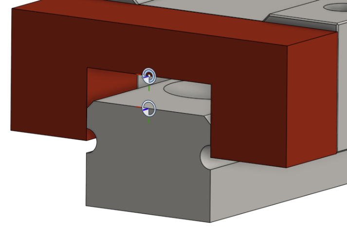
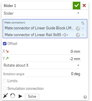
So what would a sane person think the mate would move? Right: down the rail. Well aside that it would be more intuitive for a slider to mate the top part of a rail to the bottom of a slider, but that's beside the point.
But where does it really move? Right! The opposite direction. *Faceplam*
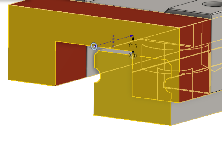
So you have to live with negative movements, or … flip the axis. You would assume, flipping the axis would just invert the movement direction, but no, instead it does this:
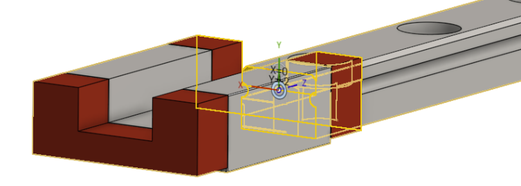
Welcome to FYL. … Ok, then rotate the secondary axis then (twice): And you end up with:
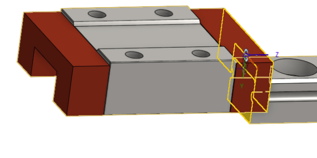
AND THERE IS NO Z OFFSET! Oh, no, that would make it too easy.
Instead, you have to go into the mate connector, edit that, choose move there and pray, that your part is one with a neat length. If you ever designed a part that has to go at an angle between "part A" and "part B" you might end up with a weird fraction. Have fun dial that in.
The real "fun" begins if you have linkages linked … in a "circle". Like: part A is connected to part B, part B is connected to part C, part C to part D, and part D is connected back to part A. The slightest aliment error, and onshape will complain everything is wrong. Good luck finding the mistake on more complicated assemblies.
Or when using imported parts, you don't have detailed sketches of (and hence dimensions are a bit of guesswork or turning them back into sketches).
I tried to update my primitive slider* with that prefab linear rail.
*= In a construct that converts linear motion to rotational.
My construct turns a ~70 mm linear motion into a ~170 deg rotational one (base to yellow arm) without taking up too much space vertically.

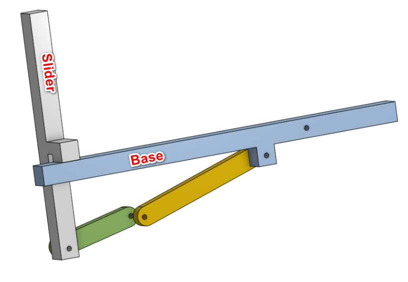
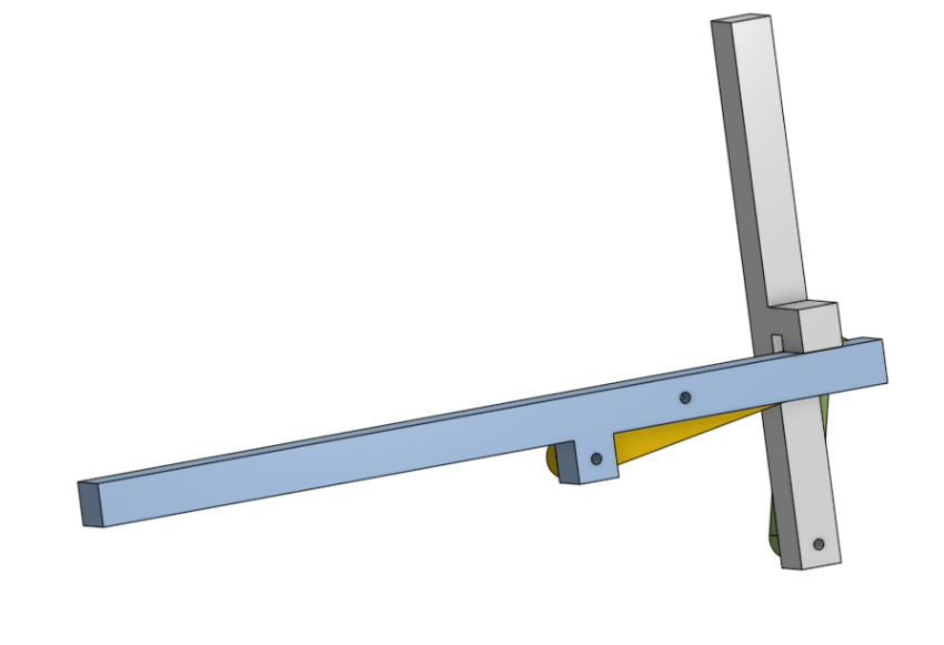
And this is the result: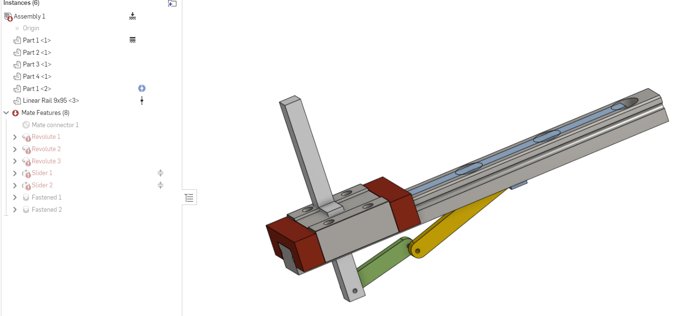
Possible solutions to make it work:
Let's open the can of worms that is Named Positions. As simple as the idea is: Safe movement states for later. As broken it is.
(To follow along, please look at the pictures without the commercial rail)
I had to define the angle of the yellow arm on top of the slider position: Or the link would bend randomly in the wrong direction (I was unable to predict when and why), or would report a movement isn't possible. Even if animate did it just fine, and so did the part movement tool.
Even then, I will get in states where it proudly proclaims: Movement not possible. I have to grab the part and move it just a tiny bit manually, and then it works. TH!
As so often, the devil is in the detail.
Have two parts that already in the position they should be in? Good effing luck connecting them with mates. I constantly get rid of the first mate connector I already placed on the first part while trying to place the second mate connector on the second part. And then the order the mate connectors are listed matter. And while you can change that after the fact, I have a sneaking suspicion it differs (even if it shouldn't) if you add them in the correct order, or if you add them in the wrong order and reorder them later in that list.
And then you run into the issue that the freshly placed mates are moving in the wrong direction. So you either have to live with a negative rotation, or flip that axis (I come back to that later). And negative rotation breaks limits. Because the minimum angle of a rotation has to be bigger than the maximum. Makes sense. Except it doesn't because limiting a rotation from 0 deg to -150 deg DOES NOT EQUAL the limit from -150 deg to 0 deg. The former does move, the latter doesn't.
And don't get me started on sliders. (Too late)
Here is how a sane person mates a slider (in image with a Y offset, as overlapping structures [mates] are hard to see):


So what would a sane person think the mate would move? Right: down the rail. Well aside that it would be more intuitive for a slider to mate the top part of a rail to the bottom of a slider, but that's beside the point.
But where does it really move? Right! The opposite direction. *Faceplam*

So you have to live with negative movements, or … flip the axis. You would assume, flipping the axis would just invert the movement direction, but no, instead it does this:

Welcome to FYL. … Ok, then rotate the secondary axis then (twice): And you end up with:

AND THERE IS NO Z OFFSET! Oh, no, that would make it too easy.
Instead, you have to go into the mate connector, edit that, choose move there and pray, that your part is one with a neat length. If you ever designed a part that has to go at an angle between "part A" and "part B" you might end up with a weird fraction. Have fun dial that in.
The real "fun" begins if you have linkages linked … in a "circle". Like: part A is connected to part B, part B is connected to part C, part C to part D, and part D is connected back to part A. The slightest aliment error, and onshape will complain everything is wrong. Good luck finding the mistake on more complicated assemblies.
Or when using imported parts, you don't have detailed sketches of (and hence dimensions are a bit of guesswork or turning them back into sketches).
I tried to update my primitive slider* with that prefab linear rail.
*= In a construct that converts linear motion to rotational.
My construct turns a ~70 mm linear motion into a ~170 deg rotational one (base to yellow arm) without taking up too much space vertically.


And this is the result:

Possible solutions to make it work:
- Get Fastened 2 aligned correctly (it connects the commercial rider to my one), which is near impossible.
- Delete/suppress Fastened 2, not an option, that makes the commercial rider move in sync.
- Suppress/delete Slider 1. Not an option, it has the constraints and is part of Named Positions (another can of worms*)
- Delete/suppress Fastened 2, not an option, that holds the commercial rail in place.
- Suppress/delete the redundant Slider 2. (Which is what I did, but I should not have been forced to. Slider 1 and 2 move in parallel).
Let's open the can of worms that is Named Positions. As simple as the idea is: Safe movement states for later. As broken it is.
(To follow along, please look at the pictures without the commercial rail)
I had to define the angle of the yellow arm on top of the slider position: Or the link would bend randomly in the wrong direction (I was unable to predict when and why), or would report a movement isn't possible. Even if animate did it just fine, and so did the part movement tool.
Even then, I will get in states where it proudly proclaims: Movement not possible. I have to grab the part and move it just a tiny bit manually, and then it works. TH!
-1
Comments
As far as your assembly errors go, I suspect the revolutes are fighting each other (in the Z-direction), if you change the one between the green and yellow arms to a cylindrical mate it should help things...
As far as mating things, it's easier to start the mate with the parts NOT in the correct final position. This solves trying to select overlapping things.
You are correct that the order of selection matters and it does affect how offset work. Basically the offset is going to be applied based on the axes of the first mate connector you select, and they are also going to be applied TO the first mate connector you pick. So you want to pick the "moving" part (the one you are mating) first and the "fixed" (the one you are mating to) second.
See this video for discussion about this:
The new addition of being able edit mate connectors during the mating process means you can now re-align your first mate connector before picking the second one in order to get predictable offsets and behavior. Adding an explicit mate connector in the part studio is also a good way to get better control of that.
Looking at your profile your just started with Onshape, give it some time and please be nice on this forum