Welcome to the Onshape forum! Ask questions and join in the discussions about everything Onshape.
First time visiting? Here are some places to start:- Looking for a certain topic? Check out the categories filter or use Search (upper right).
- Need support? Ask a question to our Community Support category.
- Please submit support tickets for bugs but you can request improvements in the Product Feedback category.
- Be respectful, on topic and if you see a problem, Flag it.
If you would like to contact our Community Manager personally, feel free to send a private message or an email.
Ribs connecting two lofts?
 RV_Driver
Member Posts: 7 ✭
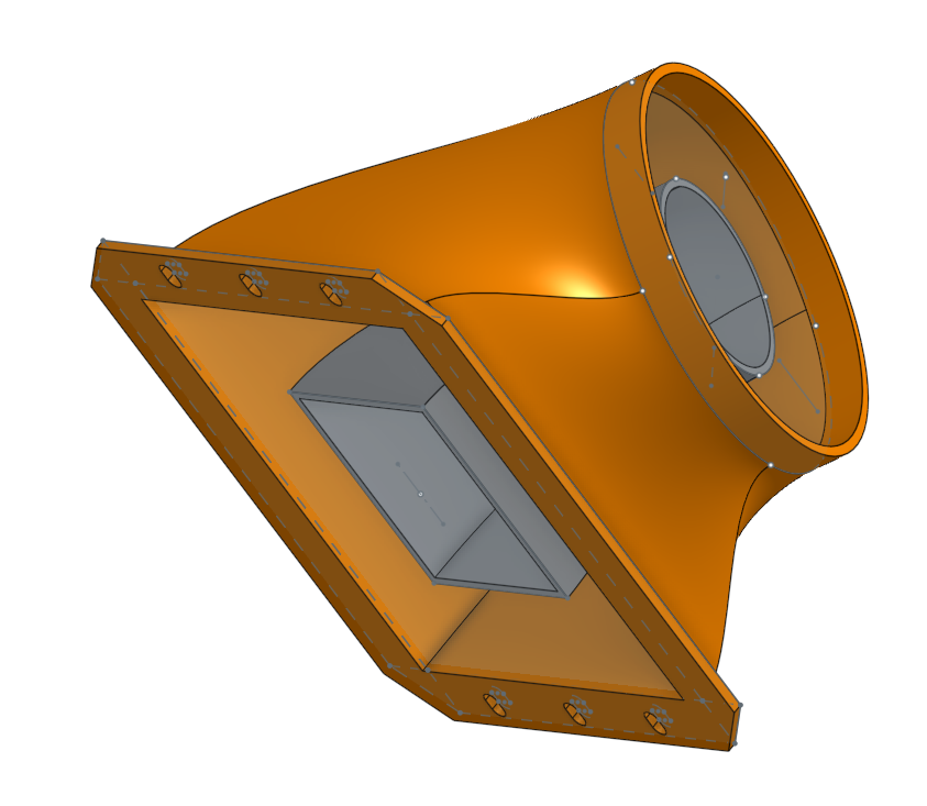
Hello. Is it possible to create ribs that join two lofts (when one left is embedded in another) and have those ribs follow the curvature of the two lofts?
In this part, what I would like is ribs normal to the outside surface of the inner loft that connects to the inside surface of the outer loft (a total of four ribs, one each every 90 degrees). And I would like for those ribs to follow the curvature of the lofts, rather than just be linear. Basically, the ribs would function as vanes to 1) fix and suspend inner loft to the entire part and 2) help control airflow through the part.
If that's possible, how might I do that?
Thanks for the suggestions.

0
Best Answers
-
 glen_dewsbury
Member Posts: 1,247 PRO
-
 john_lopez363
Member Posts: 139 ✭✭✭
@RV_Driver
Here is another approach. Same results, much more efficient process and Feature Tree (about 1/2 as many Features).
https://cad.onshape.com/documents/6711b5b9f2beca5f48d427c2/w/cb56af28a5fc5cd443c64bb2/e/3fa9c381dd132e83e0242839
2 -
 glen_dewsbury
Member Posts: 1,247 PRO
RV. John is correct about the number of features. That why I gave him a vote up.
For my own curiosity I played around with this a bit more and got about the same number of features by starting new.
For better examples of feature builds have a look at John's and this version from me. There's usually more than one way to skin a cat. You'll decide with time what your wants and needs are.
https://cad.onshape.com/documents/26e53ab936bbe1172c990b0e/w/d0289eff260df54f6ba5727b/e/35536d39770e666edf7937a2
1 -
 john_lopez363
Member Posts: 139 ✭✭✭
@RV_Driver
Nice job picking up on some of the techniques...one of the simplest is the use of Folders to organize your Feature Tree, another is giving logical names to all of the Features.So here's a little feedback as well as a couple of solutions:
- It's really important to fully constrain all of your Sketches.
- Use good Top-Down modeling techniques when possible.
- You had some misalignment of various Sketch's. One result of this is what caused the Inner Body Loft Remove to get a bit wonky. Easily solved with top-down modeling techniques.

So for the solutions...there's a couple things going on here.
The fundamental issue was introduced by changing the thickness of the Main Body Shell (you made it thinner). Doing this it caused the Inner Bodies to no longer fully intersect with the Outer Body. This causes the "Add" boolean operator of the Inner Body Solid Loft feature to fail. A way to troubleshoot this is to change the Inner Body Solid Loft feature to use the "New" boolean operator (instead of Add). As you can see the Loft generates fine doing it this way, which tells you the Loft itself is ok.- Another way to test this is by making the Shell thickness a little larger, try 0.125".

The fillets in general in this model are prone to intersecting geometry issues (given all the curvatures).- The Main Body Inner Front fillet's can be solved by using a "Partial Fillet"...albeit you will need separate fillets, one for each side (left side of screenshot).
- The Inner Body fillets (especially the ones that intersect the larger radius bend of the Outer Body) are suffering from the intersecting geometry issues, Again, I solved this by tinkering with various options of the Partial Fillets operator (see doc link for how-to).

Lastly, here is a new link if you need to see how I did it.
https://cad.onshape.com/documents/f4205471a796baf0da4e5237/w/03ffc70f306e8dc4e62dd371/e/0f9234e653e8b2d1fadedd2c
4 -
 glen_dewsbury
Member Posts: 1,247 PRO
Nice job John. I was too slow this afternoon with my response. My results were very similar.
To reiterate some of John's notes.
Sketches want to be fully constrained starting from the origin to keep alignment. Some of yours looked eye balled into place so results aren't as expected. Use of mirroring and patterning keeps the number of updates to a minimum.
Use of variables can be a big time saver. In this case I made the walls and ribs and some fillets with this so features update without editing individual features.
The rib loft doesn't seem to behave as expected. (I think a nonmanifold condition) Extending the rib sketch a bit into the walls seems to take care of that.
Structured feature list with named features list can be very helpful. Feature lists can grow to a length that is annoying to manage for more complex multipart studios.
Complete main features in the simplest form possible. Add things like filets and chamfers later
I like to use a sketch that allows using a implicit mate connecter for sketch planes. I find this simpler and cleaner than multiple planes and provides a fixed center for the sketch. Easy to modify with the final button checked to see results.
https://cad.onshape.com/documents/2b6c34886048d3ad4e270f3d/w/d9373353570e6e9349b90f5d/e/8615d68b39b8c0fff11d8ae6
1

Answers
https://cad.onshape.com/documents/26e53ab936bbe1172c990b0e/w/d0289eff260df54f6ba5727b/e/91cbe6dc3350bb3477d5f80a
Here is another approach. Same results, much more efficient process and Feature Tree (about 1/2 as many Features).
https://cad.onshape.com/documents/6711b5b9f2beca5f48d427c2/w/cb56af28a5fc5cd443c64bb2/e/3fa9c381dd132e83e0242839
For my own curiosity I played around with this a bit more and got about the same number of features by starting new.
For better examples of feature builds have a look at John's and this version from me. There's usually more than one way to skin a cat. You'll decide with time what your wants and needs are.
https://cad.onshape.com/documents/26e53ab936bbe1172c990b0e/w/d0289eff260df54f6ba5727b/e/35536d39770e666edf7937a2
Thanks to you both for demonstrating this for me.
I needed to change some dimensions and took it as an opportunity to learn from what you guys shared with me: I rebuilt the whole piece from scratch following your work. Though it vaporized the entire day for me, it was an awesome education!
There are two hangups I'm having though:
- I can't seem to get the "Body solid loft" to generate. Do you have any thoughts on what I'm missing? It seems like the connections are properly matched so I'm not seeing where the issue is.
- This is minor and if it isn't possible, it's okay. I can't get "Interior front" fillets to generate. The error says the radius is too large, but bringing it lower and lower doesn't seem to help.
I am very grateful for your help thus far. It's been a wonderful learning experience to follow you what you both have shared!https://cad.onshape.com/documents/784697779bb35f0d7e3b6623/w/1738c3dba972e7bbb54720ba/e/31f8f9db37faa16fd9f1abfc
Nice job picking up on some of the techniques...one of the simplest is the use of Folders to organize your Feature Tree, another is giving logical names to all of the Features.
So here's a little feedback as well as a couple of solutions:
- It's really important to fully constrain all of your Sketches.
- Use good Top-Down modeling techniques when possible.
- You had some misalignment of various Sketch's. One result of this is what caused the Inner Body Loft Remove to get a bit wonky. Easily solved with top-down modeling techniques.
Here is a screenshot showing some top-down modeling techniques. The upper left part shows all three Bottom Profile sketches at once. See how all the sketches aligned precisely to each other. Lower right part shows all three of the Upper Profile sketches, again all align to each other.So for the solutions...there's a couple things going on here.
The fundamental issue was introduced by changing the thickness of the Main Body Shell (you made it thinner). Doing this it caused the Inner Bodies to no longer fully intersect with the Outer Body. This causes the "Add" boolean operator of the Inner Body Solid Loft feature to fail. A way to troubleshoot this is to change the Inner Body Solid Loft feature to use the "New" boolean operator (instead of Add). As you can see the Loft generates fine doing it this way, which tells you the Loft itself is ok.- Another way to test this is by making the Shell thickness a little larger, try 0.125".
Assuming the thickness of the Main Body needs to be (.0625"), the best way to resolve this is to make the length of the fins on the Inner Body parts slightly longer...at both the Bottom Profile sketch and the Top Profile sketch. Here is the example of the Inner Bottom Profile sketch.The fillets in general in this model are prone to intersecting geometry issues (given all the curvatures).
Lastly, here is a new link if you need to see how I did it.
https://cad.onshape.com/documents/f4205471a796baf0da4e5237/w/03ffc70f306e8dc4e62dd371/e/0f9234e653e8b2d1fadedd2c
To reiterate some of John's notes.
Sketches want to be fully constrained starting from the origin to keep alignment. Some of yours looked eye balled into place so results aren't as expected. Use of mirroring and patterning keeps the number of updates to a minimum.
Use of variables can be a big time saver. In this case I made the walls and ribs and some fillets with this so features update without editing individual features.
The rib loft doesn't seem to behave as expected. (I think a nonmanifold condition) Extending the rib sketch a bit into the walls seems to take care of that.
Structured feature list with named features list can be very helpful. Feature lists can grow to a length that is annoying to manage for more complex multipart studios.
Complete main features in the simplest form possible. Add things like filets and chamfers later
I like to use a sketch that allows using a implicit mate connecter for sketch planes. I find this simpler and cleaner than multiple planes and provides a fixed center for the sketch. Easy to modify with the final button checked to see results.
https://cad.onshape.com/documents/2b6c34886048d3ad4e270f3d/w/d9373353570e6e9349b90f5d/e/8615d68b39b8c0fff11d8ae6
The point about the top-down approach is well taken. And I love the variable approach.
I can't thank you both enough for taking the time to help me. I hope this thread helps others too as you've deposited so many great tips and examples. I genuinely appreciate your time and thoughts.
This was my first go at 3D design and it was so much fun. What a cool skill to start learning!