Welcome to the Onshape forum! Ask questions and join in the discussions about everything Onshape.
First time visiting? Here are some places to start:- Looking for a certain topic? Check out the categories filter or use Search (upper right).
- Need support? Ask a question to our Community Support category.
- Please submit support tickets for bugs but you can request improvements in the Product Feedback category.
- Be respectful, on topic and if you see a problem, Flag it.
If you would like to contact our Community Manager personally, feel free to send a private message or an email.
Aligning multiple derived parts by a point
 grzegorz_zdanowski
Member Posts: 5 EDU
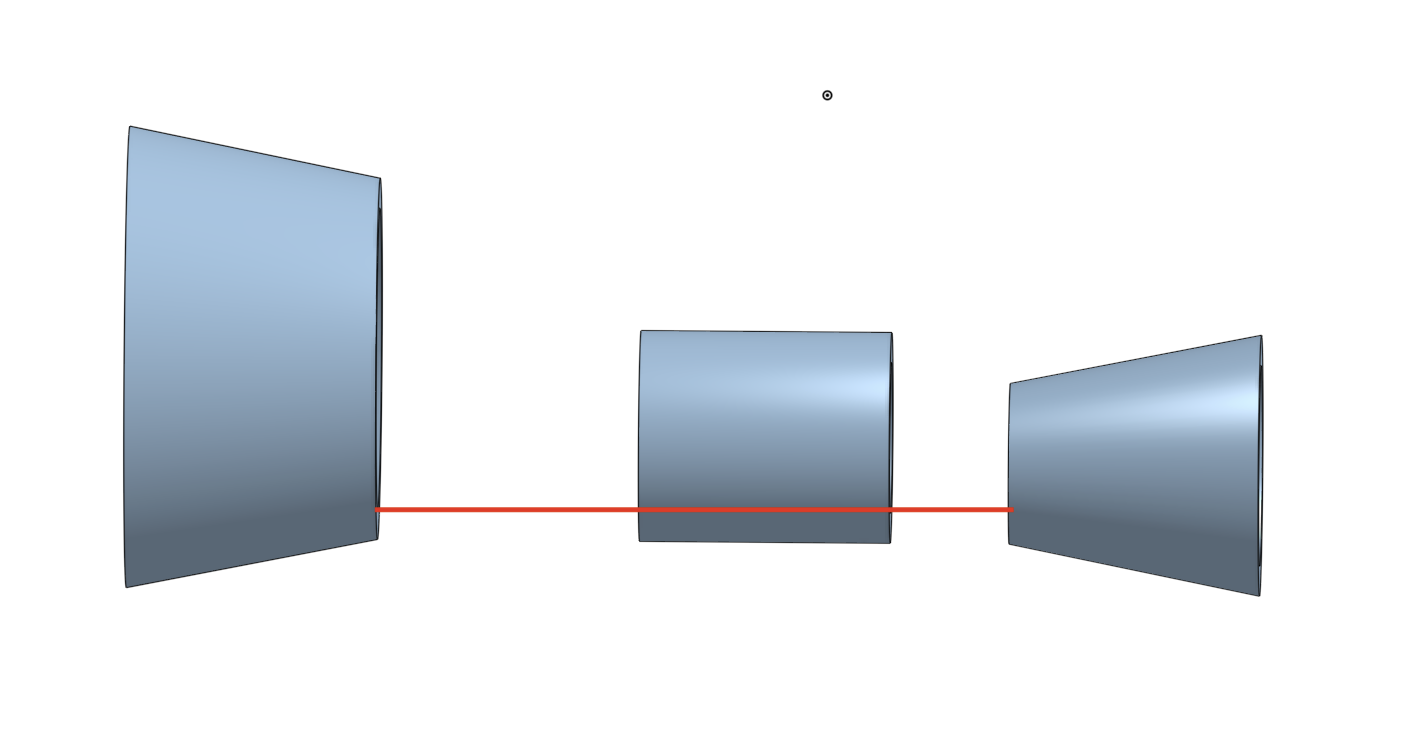
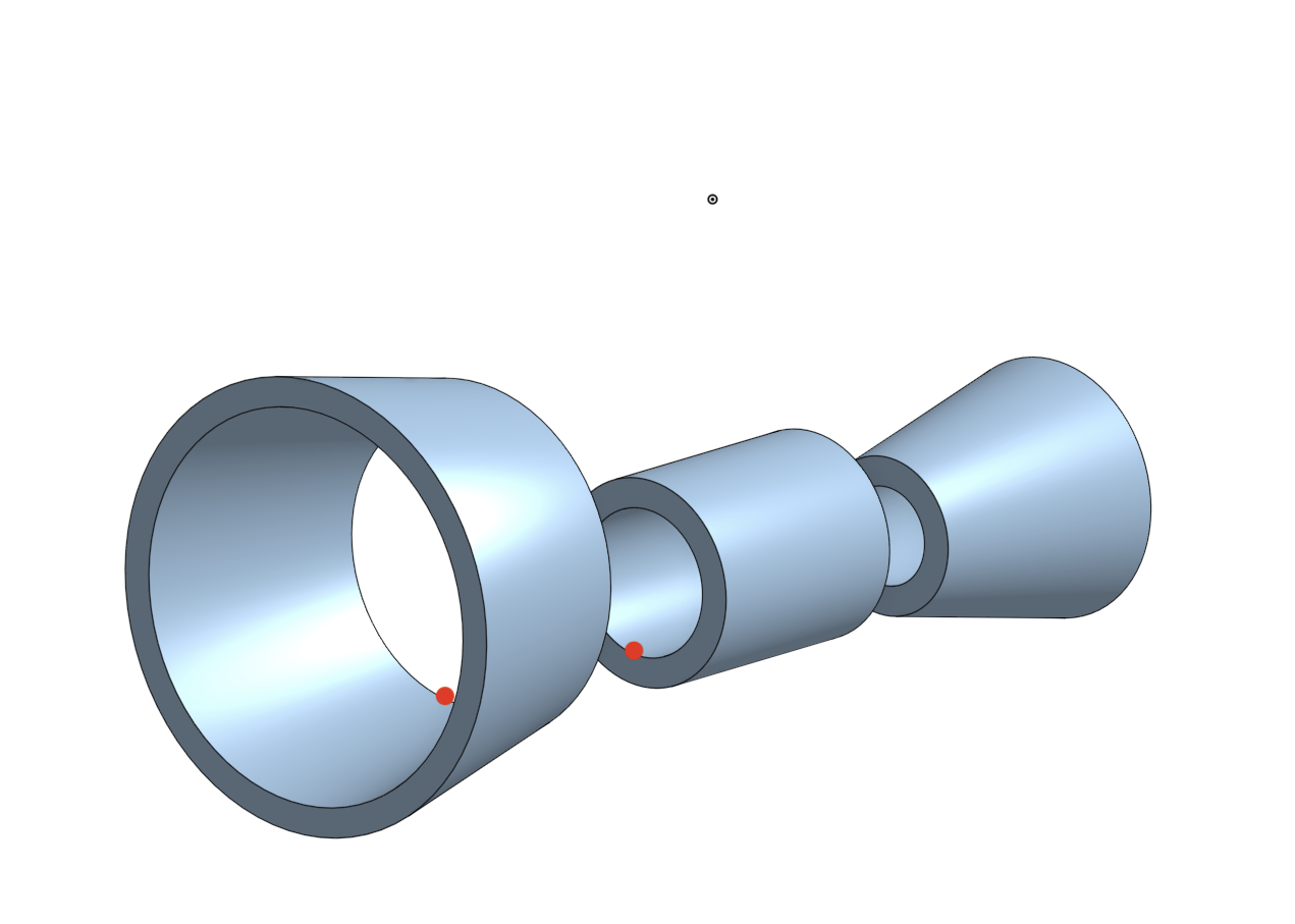
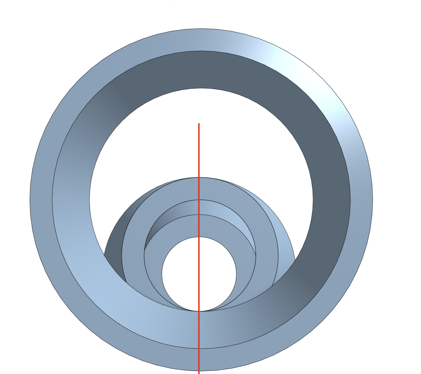
I have a hypothetical pipes & cones that are of a different size. I want to align them in a separate part studio as derived parts. The biggest issue I'm facing is I need to align them based not on the center of the holes but based on the "bottom edge" point of the circle. What I did as a proof-of-concept to show my desired result is hand-move them in assembly 
The reason why I want to align them like that in another part studio is these are just small sub-parts. I want to derive them and boolean them for manufacturing.
View from the side - all aligned

These are the points I want to be in the same line

View from the side how they're aligned

Demo document: https://cad.onshape.com/documents/59af9c98f8f2a9bdd2b694c0/w/5644a69aac0b68dc5d5d5278/e/0e0cc3212015534e592920d9
Naturally, I can brute-force that with manual transformations (or even some clever measured variables), but this feels like a massive kludge. I tried using mate connectors and locations but no matter what I do I can never achieve alignment, but rather parts "semi randomly" rotating
The reason why I want to align them like that in another part studio is these are just small sub-parts. I want to derive them and boolean them for manufacturing.
View from the side - all aligned

These are the points I want to be in the same line

View from the side how they're aligned

Demo document: https://cad.onshape.com/documents/59af9c98f8f2a9bdd2b694c0/w/5644a69aac0b68dc5d5d5278/e/0e0cc3212015534e592920d9
Naturally, I can brute-force that with manual transformations (or even some clever measured variables), but this feels like a massive kludge. I tried using mate connectors and locations but no matter what I do I can never achieve alignment, but rather parts "semi randomly" rotating
0
Answers
https://cad.onshape.com/documents/7ab949c862873021d13a9496/w/b2b86fd41feb35c300aa3047/e/c11659bdb5378789aaa07e13?renderMode=0&tangentEdgeStyle=1&uiState=668057e170111052c125d39c
or you could pick the origin of the destination PS as a reference instead (and adjust the MC):
https://cad.onshape.com/documents/7ab949c862873021d13a9496/w/b2b86fd41feb35c300aa3047/e/c6a0fe4039b79335ec1ddf63?renderMode=0&tangentEdgeStyle=1&uiState=6680581a70111052c125d3b3