Welcome to the Onshape forum! Ask questions and join in the discussions about everything Onshape.
First time visiting? Here are some places to start:- Looking for a certain topic? Check out the categories filter or use Search (upper right).
- Need support? Ask a question to our Community Support category.
- Please submit support tickets for bugs but you can request improvements in the Product Feedback category.
- Be respectful, on topic and if you see a problem, Flag it.
If you would like to contact our Community Manager personally, feel free to send a private message or an email.
Newbie Question: How do I create a sketch plan at 90 degrees to a face?
 john_smith077
Member Posts: 175 ✭✭✭
Hello
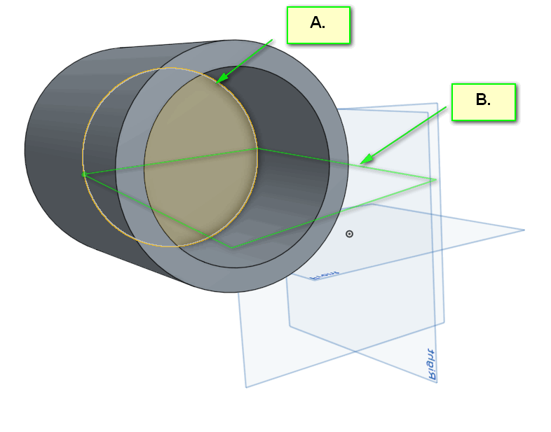
Please excuse this newbie question, but if I select a plane (e.g. "A.") and want to create a sketch plane at 90 degrees to it, how do I achieve this?
Obviously one solution would be to draw a square, extrude it a bit, then select one of the faces of the new square to draw then next Sketch face on. But this seems cumbersome and I would then end up with unwanted geometry in my model...

e.g. Should I move the Origin for the entire model to the center of my hollow cylinder (above), and then click on one of the planes (in pale blue)? Or would that screw up all my parametric dimensions?
I told you it was a basic question!
Many thanks
J
Please excuse this newbie question, but if I select a plane (e.g. "A.") and want to create a sketch plane at 90 degrees to it, how do I achieve this?
Obviously one solution would be to draw a square, extrude it a bit, then select one of the faces of the new square to draw then next Sketch face on. But this seems cumbersome and I would then end up with unwanted geometry in my model...

e.g. Should I move the Origin for the entire model to the center of my hollow cylinder (above), and then click on one of the planes (in pale blue)? Or would that screw up all my parametric dimensions?
I told you it was a basic question!
Many thanks
J
0
Best Answer
-
 øyvind_kaurstad
Member Posts: 234 ✭✭✭
And to the OP, if the plane you are after is parallell to one of the default planes (which it looks like it is), you can use "Plane point", with the chosen default plane and the center point of your circle (might have to unhide the sketch to see the point). Like so:
7
Answers
2. If your new plane is parallel to an existing plane then you should be doing an offset from that existing plane. Otherwise you'd need a line or a set of points in addition to a plane in order to define the new plane. In common practice it is infrequent that one would have to define new planes, especially if the new planes are parallel to existing ones.
3. As you learn more about parametric modeling you'll develop better techniques. Using the origin to constrain the center of a circle is just one of the more obvious ones that you haven't yet picked up on. It appears that the plane you are trying to add would already be there if you had started your sketch centered on the origin.
If it is possible to sketch on a part surface I will of course not create a new plane for that, but that's not always possible.
I am confused - are you saying that I should move the XYZ origin to wherever the new sketch plane is? And if so how is that done?
øyvind_kaurstad
Yes! Plane Point is exactly what I was looking for.
So to get clear: I right click on a default plane ==> "Offset plane" ==> Change "Offset" to "Plane Point" ==> Select the point I want.
Many thanks
But as I build my parts of gradually increasing complexity how should I use the XYZ 'origin'?
For best practice, should I be moving the Origin around the part, or should I just start designing part using the origin for one's first Sketch and thereafter leave the Origin in place at say one corner (or the notional centre) of the part?
My suggestions above were made based on what looks like a cylindrical part that is not centered on the origin. It appears that if your part had been started with the center of the sketched circle on the origin you could have used one of the existing primary planes for the other feature you are trying to make, rather than trying to make a secondary plane.