Welcome to the Onshape forum! Ask questions and join in the discussions about everything Onshape.
First time visiting? Here are some places to start:- Looking for a certain topic? Check out the categories filter or use Search (upper right).
- Need support? Ask a question to our Community Support category.
- Please submit support tickets for bugs but you can request improvements in the Product Feedback category.
- Be respectful, on topic and if you see a problem, Flag it.
If you would like to contact our Community Manager personally, feel free to send a private message or an email.
Arranging points in space, for simple design using Frame tool.
 jan_vil
Member Posts: 9 ✭
jan_vil
Member Posts: 9 ✭
Beginner here. I'm having trouble wrapping my head around this simple thing - as I understand sketches can exist on one 2D plane, and they can't be moved?
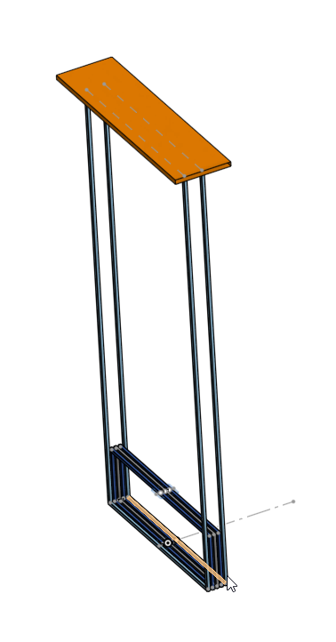
Lets take this shelf as an example I built some time ago

What would be the best way in designing a simple shape like this using frames?
With this certain example I had 2 constraints - height of the top surface, and width of the whole piece.
Reason for cad design would be to play around with the proportions and get a cut list with angles.
Lets say I start with a sketch on the Right plane with a rectangle for the 'bigger' outer frame. What would be the next step in making one of the 'smaller' rectangles, while keeping it procedural in the sense that I could change the number of smaller inner rectangles later on, to see what looks best?
And also the top surface - how can I make a sketch for the top surface which is perpenticular to the first sketch but offset a certain amount?
Sorry if this is answered multiple times before.
Best Answers
-
jnewth
Member, OS Professional Posts: 130 PRO
Here's an example of how to start doing something like this.
https://cad.onshape.com/documents/cfbbef8c4c975a1111697473/w/14f3b05708dea10e8346273e/e/1b97b4ffeeb11e06c9944871First, you are partially right: Sketches are made on planes. However, you can create planes anywhere you want (or use mate connectors - but that's a subject for another time).
Second: Sketches can be moved, but (usually) don't do that. There's no need.Third: Frames are a powerful way to make lots of related parts, but eh, take a bit of tinkering to understand how they work. Would recommend you take a peek at the learning center and tinker with simple frames to get a sense for how they work.
In terms of basic modeling you can accomplish this in many many different ways. Your parts do exist on different planes, so you could organize this front to back (as if you were standing in front of the table and making slices) or top to bottom. I chose top to bottom.
I laid out the "base sketch" to have the 5 long segments defined in that sketch. I also did something curious: I created points (sketch points) at the intersection where i want that cross piece to run. What this will help me do later on is define all those small segments you make to join the larger rectangles together.
I then made some new plane "the mid plane" and the "benchtop plane" which represents the top plane of the smaller rectangles and the top of the frame (just beneath the wood panel). On those sketches I use the "use" sketch feature (youll want to look that one up) and transferred some of the contents of the base sketch to those sketches. If you can roll back to where that mid sketch is in the feature tree youll see the "skeleton" of the frame.Then I went ham and made a bunch of frames. You can use a single frame feature to make a bunch of frame pieces but there are some limits to what can be done. So I basically make one at a time. I also made use of a few mirror operations (because this thing has multiple planes of symmetry it's easy and efficient to do this, but not strictly necessary). Last, I used a frameTrim operation to make all those small sections.
Here's the skeleton sketches and the top, mid and benchtop planes:
Then here's the result of 3 frame operations (youll want to open one up to see that I used a mixture of point and sketch edges to tell it how to make the segments).

Then a mirror operation because who's got the time:

Then a couple more bits and bobs to make the top panel.

Throughout the model and feature tree you'll see variables like #length = 60in and #width = 24in. These are useful because we can set dimensions as variables in the feature tree, and then use them when we are drawing sketches or defining features, and then we can mess with them to quickly look at how different dimensions would look. For example: here's a 12 ft tall table that's 6inches wide with a 6in wood overhang:
Anyhow, fun to play with!
Also: I think this table you made looks very beautiful. If you do commissions, let's talk. Hit me up on DM.

Anyhow, take a peek at that doc I shared, make a copy, futz with it a bit. Should get you started on figuring out how to do your own CAD for this. Frames in particular benefit from a few examples to explain some of its shortcomings / understand some of its limitations.1

Answers
Here's an example of how to start doing something like this.
https://cad.onshape.com/documents/cfbbef8c4c975a1111697473/w/14f3b05708dea10e8346273e/e/1b97b4ffeeb11e06c9944871
First, you are partially right: Sketches are made on planes. However, you can create planes anywhere you want (or use mate connectors - but that's a subject for another time).
Second: Sketches can be moved, but (usually) don't do that. There's no need.
Third: Frames are a powerful way to make lots of related parts, but eh, take a bit of tinkering to understand how they work. Would recommend you take a peek at the learning center and tinker with simple frames to get a sense for how they work.
In terms of basic modeling you can accomplish this in many many different ways. Your parts do exist on different planes, so you could organize this front to back (as if you were standing in front of the table and making slices) or top to bottom. I chose top to bottom.
I laid out the "base sketch" to have the 5 long segments defined in that sketch. I also did something curious: I created points (sketch points) at the intersection where i want that cross piece to run. What this will help me do later on is define all those small segments you make to join the larger rectangles together.
I then made some new plane "the mid plane" and the "benchtop plane" which represents the top plane of the smaller rectangles and the top of the frame (just beneath the wood panel). On those sketches I use the "use" sketch feature (youll want to look that one up) and transferred some of the contents of the base sketch to those sketches. If you can roll back to where that mid sketch is in the feature tree youll see the "skeleton" of the frame.
Then I went ham and made a bunch of frames. You can use a single frame feature to make a bunch of frame pieces but there are some limits to what can be done. So I basically make one at a time. I also made use of a few mirror operations (because this thing has multiple planes of symmetry it's easy and efficient to do this, but not strictly necessary). Last, I used a frameTrim operation to make all those small sections.
Here's the skeleton sketches and the top, mid and benchtop planes:
Then here's the result of 3 frame operations (youll want to open one up to see that I used a mixture of point and sketch edges to tell it how to make the segments).
Then a mirror operation because who's got the time:
Then a couple more bits and bobs to make the top panel.
Throughout the model and feature tree you'll see variables like #length = 60in and #width = 24in. These are useful because we can set dimensions as variables in the feature tree, and then use them when we are drawing sketches or defining features, and then we can mess with them to quickly look at how different dimensions would look. For example: here's a 12 ft tall table that's 6inches wide with a 6in wood overhang:
Anyhow, fun to play with!
Also: I think this table you made looks very beautiful. If you do commissions, let's talk. Hit me up on DM.
Anyhow, take a peek at that doc I shared, make a copy, futz with it a bit. Should get you started on figuring out how to do your own CAD for this. Frames in particular benefit from a few examples to explain some of its shortcomings / understand some of its limitations.
Here is another way to reflect on.
https://cad.onshape.com/documents/218468ed865c18da8c63a862/w/7df381bb818b90b3211ce32c/e/92171c66e9b4823cb7343498
Thank you for the amazing answers!
Some great info in this thread and great example projects.
Variables is something I didn't know of before and having a look in jnewth's project it makes much sense now.
Why I didn't want to use mate connectors or offset planes was that it 'felt' weird to go and change certain meausrements in Sketch options panel, and some measurements in the sketch itself.
But Is there a way in making linear patterns or mirrors of just points or lines, rather than geometry? Let's say i want to achieve something like the pipes screensaver from way back.
all the 'corners' are locked to a grid pattern, with certain spacing. And I could just add frames between the points that are already existing in 3d space. Do i need to create a new sketch manually for all the planes (horizontally or vertically)?
You can create a frame member between 2 points (no need for a line). So create a single point on your origin and use a linear pattern to create your grid, (you will need a second pattern for the "z" direction).
Here's an example: https://cad.onshape.com/documents/cfa9fe303d7591c93605b8c2/w/eb60530d4a9bef0f3e9a71cc/e/a2d0c6f5f3886a4234eee1b8
Also have a look at the "routing curve" feature for something like this…
For sure you can - but it's a tricky workflow imo. I made a sketch with a 2D pattern of points, then patterned that sketch, creating a 3D grid of points. It is tricky to navigate but works:
I think you could make some sweet art pieces with this approach but the performance on the sketch pattern isnt wonderful. I dont know though - try it out and report back!
Here's a share that shows what I did:
https://cad.onshape.com/documents/f4549832238243d0f9c8ac66/w/2d296e0ad76491195d9ded6e/e/0c5274afd2e4a0f4e99e5f8a
@jnewth,
That looks similar to what I did, it does get hard to see what points your are picking though!
Using the routing curve and and using a "pitch" variable (with a multiplier for each step) for the relative offset is an cleaner way to do this:
https://cad.onshape.com/documents/cfa9fe303d7591c93605b8c2/w/eb60530d4a9bef0f3e9a71cc/e/aa721bcd3179370126b9e143?renderMode=0&tangentEdgeStyle=1&uiState=67f461e156ed9270a333d5bd
@eric_pesty that looks quite a bit more manageable!