Welcome to the Onshape forum! Ask questions and join in the discussions about everything Onshape.
First time visiting? Here are some places to start:- Looking for a certain topic? Check out the categories filter or use Search (upper right).
- Need support? Ask a question to our Community Support category.
- Please submit support tickets for bugs but you can request improvements in the Product Feedback category.
- Be respectful, on topic and if you see a problem, Flag it.
If you would like to contact our Community Manager personally, feel free to send a private message or an email.
Any tips for performance / rebuild improvement?
 sam_wehrli
Member Posts: 15 PRO
sam_wehrli
Member Posts: 15 PRO
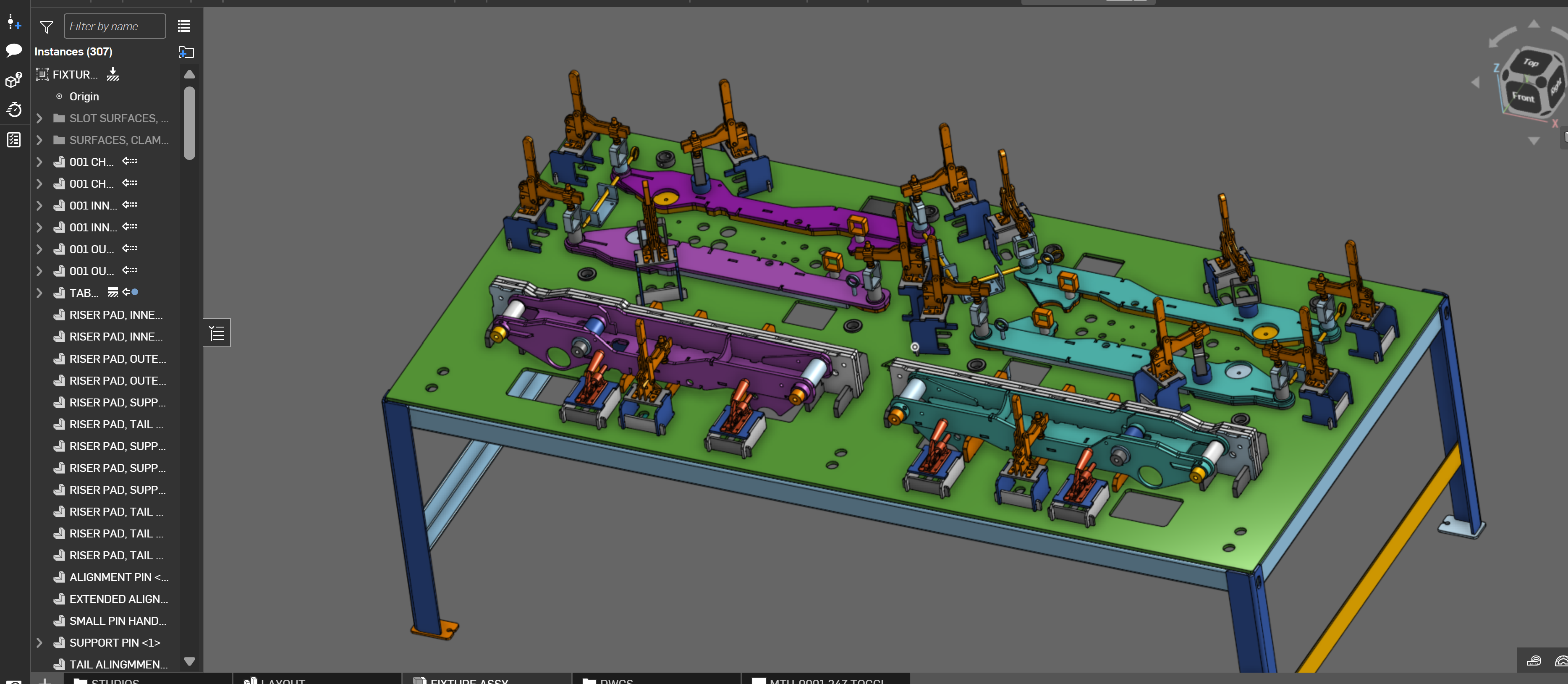
I design fixturing and work holding for a manufacturing company. My usual work flow with OS is designing around an imported part, or weldment in this case. I tend to have one parent "LAYOUT" studio with some sort of fixture base, and the parts to be held positioned in relationship to the base. I then design all the clamping and supporting parts and widgets in separate part studios, and mate them together in a final assembly.
The last step in my flow is to use contextual references to "cut" the locating features into the primary fixture base which is typically a laser cut part of some sort.
I do some machine work, attach some things with fasteners when tight tolerances are required but I also do a lot of "tab and slot" features for welding. My issue is : laser cutting slots in a sheet of steel, it's best to have some sort of filleted corner relief, no hard 90s. Bringing the laser to a zero point results in "slag-cicles" that cause interference.
I've tried doing this with traditional sketch geometry, but all those sketch fillets really start to lag the system. This one was a pretty large table fixture, and there were so many that I decided to actually try some surfacing ribbons in the shape of the slot at the part studio level, then just "use/project" each one into the parent studio. That helped a little, but I'm still dealing with 20+ seconds for rebuilding after an edit. Updating the context sometimes takes a minute or more.
If anyone has any tips to improve this flow, I'm open to ideas. I build plenty of smaller jigs that this isn't an issue at all, but I find myself wondering how some companies deal with truly large assemblies.
Thanks for any help!


Comments
You could try the CNC Overcuts feature. I used to have a crazy 4 step process in Solidworks to make this kind of geometry and now it's just a matter of selecting the parts you want overcut and letting the feature do the work. I made a custom version of it to patch in support for sheet metal parts as well as letting the tool skip past parts that don't require overcutting since the original tool will just fail if it doesn't find any corners to munch material from. Word of warning though if you've got heavy geometry in a studio before applying the corner treatment with this tool, no method of generating these corners is going to be lightweight - especially if you actually are defining your parts as sheet metal before using it. Any sheet metal operation is going to be 2-10x more computationally expensive than their non-sheet metal cousins. Your most likely solution to most performance issues is break parts out into more studios and try not to do as much in any single one.
https://cad.onshape.com/documents/ee5d9ae68845597916dabf3f/v/2792eca1b0862a414cfead02/e/54bf6bc4f243f2b48d6d0378
Derek Van Allen | Engineering Consultant | MeddlerAnother approach might be to place mate connectors where you know your fixtures will end up, create the negative of the dogbone features as you already have in another studio, and Point Derive just the cutting solids into the fixture table studio onto all the mate connector locations. This avoids the assembly context and loading all of the geometric data of an entire assembly of components all at once. Our company catalog has boolean solids defined for a lot of catalog components like bearing pockets, cam lock clearances, weird threaded insert shoulder geometry - stuff that you wouldn't want to model more than once. The solids then just permanently live in the studio with the parts they go with so there's never a need to search for em.
Point Derive is like a Derive, Transform, and Boolean operation all in one that lets you select multiple seed locations simultaneously. It's honestly so useful I'm upset it's not a default feature.
https://cad.onshape.com/documents/ad42d9d1532c5ea87446b1e8/v/852579040773e505026da438/e/8fb6f1b296e93dac01c59371
Derek Van Allen | Engineering Consultant | MeddlerI will definitely look into that custom feature, thank you! And no, they're not sheet metal parts just modelled solids, which are parted out pretty well across several individual studios. The parent studio with the main fixture base only has 65 features on the tree, and 24 of those are mate connectors and planes. (2MS each) The sketches and extrudes for the slots are the biggest load, by far.
That's a solid idea too! I will give that a shot. I knew about that feature but I've never used the negative boolean before. I'll give that a shot, though derives tend to be heavy in themselves. Thank you!
@sam_wehrli I second the CNC Overcut feature as Plan A.
If you end up wanting to go the derive route use Super Derive (this one can do the boolean too). Do a speed test. You're right to be wary of derive because the regen can get out of hand if you don't pay attention, but if the thing you're deriving is from a very simple part studio it can be quick, and if it's placing multiple instances it only takes the derive hit once and patterns them around, whereas CNC Overcut generates a new cylinder per edge.
I was curious myself so I did a comparison between them. Performance was similar (Super Derive was actually a bit faster), but CNC Overcut is better IMO because it:
Another performance tip: you can create a configuration checkbox for "development/production" where development suppresses things that are slow to regen, like the fillets on the CNC overcut. You can set the dev one to exclude from revision mgmt and BoM so you don't accidentally use it in prod.
The Onsherpa | Reach peak Onshape productivity
www.theonsherpa.com