Welcome to the Onshape forum! Ask questions and join in the discussions about everything Onshape.
First time visiting? Here are some places to start:- Looking for a certain topic? Check out the categories filter or use Search (upper right).
- Need support? Ask a question to our Community Support category.
- Please submit support tickets for bugs but you can request improvements in the Product Feedback category.
- Be respectful, on topic and if you see a problem, Flag it.
If you would like to contact our Community Manager personally, feel free to send a private message or an email.
Many problems: assembly, export
 joseph_newcomer
Member Posts: 101 ✭✭✭
joseph_newcomer
Member Posts: 101 ✭✭✭
Drawing location: https://cad.onshape.com/documents/bb62ee15a8f72336ba6a5609/w/87910df456753a607749e92d/e/87d54c90785ef1620ac2b588?renderMode=0&uiState=6878ba8215c3e95c3121a3f5
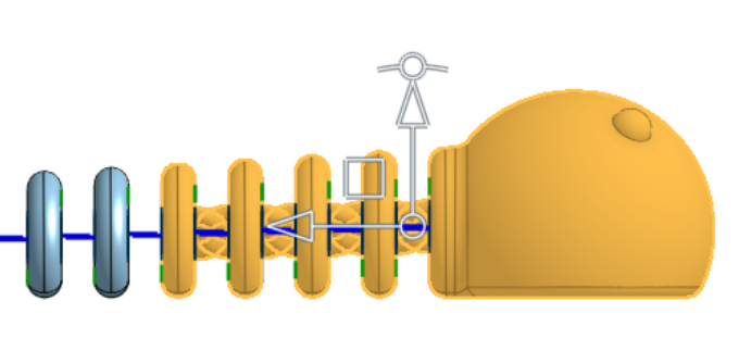
The task: make an articulated worm.
My steps:
Part studio "body"
Create a large circle on the right plane (head)
Create a plane some distance away for the tail
Create a small circle on this plane for the tail
I struggled to make a flattened circle at both ends and loft that, but gave up.
Create a plane for the loft guide
Loft to get a tapered body
I then made a cut along the top plane to remove the edge of the circle and make a flattened bottom.
Because I could not make a reference point I ended up making a separate cut to flatten the tail. I would have preferred to make a driven dimension with a name, but I can't create named driven dimensions. Grumble. For some reason, this tail cut ended up coming before the body cut. That happened a week ago, and I can't remember why.
I then made a spherical worm head.
Then I made a rectangle on the right plane and extruded it as remove to the tail plane to make the flat bottom.
I put in a plane to fix the eye positions, created the eyes, using rotate
I found that I could not replicate a pattern of a remove extrusion. Grumble. So I had to go in and make a rectangular pattern on a sketch, which I could pattern. Then I had to go back out and extrude/remove three pieces of this rectangle for each of the 18 rectangles. Painful and tedious.
In a more general case, the magic number 18 would be #number_of_segments, and 4mm would be #segment spacing, and #segment_thickness. But this is supposed to be the simple prototype.
Now I have a segmented worm.
I was hoping to be able to use a pattern to place the connectors, so I put in a "spine plane", a 3-point plane, that would mark where I wanted to replicate along. This turned out to be useless, so it is now a leftover artifact which I will remove at some point.
Next, I wanted to fillet the segments. I had to use four fillet operations because at some point I couldn't add a fillet because it gave me a violation. But if I stopped and created a new fillet, I could do a few more. Grumble.
Then I had to manually add 36 mate connectors. Tedious. Instead of being to create two and replicate them along the spine line, I had to add them one at a time. No patterning.
Part studio "Connector"
I created two semicircular connectors. They are printed at 45 degrees and are at right angles to each other. This was the simplest idea I could come up with. I'm sure there are better and much more robust ways to manage this but that's for another time.
I wanted to create them as sweeps of an elliptical shape, but when I did that, I did not get a constant diameter. So I gave up and did them as a simple rotate of a circle. I created them as front and rear connectors. I put make connectors on them.
Assembly: "Worm"
I inserted the worm body into the assembly, and fixed the head. However, each of the segments is now independent and can move, which makes no sense. I can only have one part fixed, so I can't fix any of the other parts. How can I force it to keep the spacing relationship of the original part studio object?
So I put in a few connectors. I create a solid connection (fasten) between the mate connector on the connector and the mate connector on the worm segment. After I put in four, which was incredibly tedious, I decided I had enough to test print. So I selected the head and the first four segments (using a selection box, so all the connectors were also selected) and did a right-click export.
I got a zip file downloaded, and it seems to have only one instance of front connector and one instance of rear connector, in spite of the fact that I have four instances of each in the assembly.
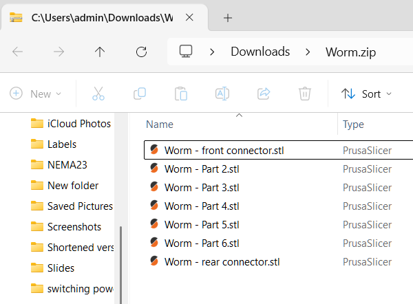
I open these files in Prusa Slicer 2.9.2 (the latest version), and it tells me that it has detected a bunch of parts, and did I want them treated as a single object? I say yes, and get what is shown in the screen shot. Two connectors, apparently in a random place.
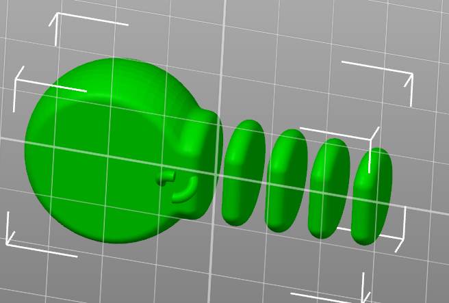
So how to I fix all of these problems? The parts all have degrees of freedom in the assembly, even though they are constrained the part studio, I don't get all my connectors, and the only two that show up are randomly placed.
Thank you in advance
Comments
Can't promise you this will print, but I took a swing at it.
https://cad.onshape.com/documents/7b265f9547ea96d0c8af0858/w/a086dde488156e48d7b16a86/e/7f7ece659de17780532738f2
Turn off export parts as unique parts when you export the STL
I don't see an option to export parts as unique parts or not
I also tried by selecting just the parts I wanted to print, right-click export on the selection, or going over to the parts list on the left and doing right-click export. No option for a single STL is presented, although the help documentation clearly shows this option.
@Matt_Shields
It seems to be printing successfully. But I don't understand what you did.
What device are you on? PC or tablet? It looks like you need to scroll down for more options. But have no scroll bar. I don't remember needing to scroll on PC.