Welcome to the Onshape forum! Ask questions and join in the discussions about everything Onshape.
First time visiting? Here are some places to start:- Looking for a certain topic? Check out the categories filter or use Search (upper right).
- Need support? Ask a question to our Community Support category.
- Please submit support tickets for bugs but you can request improvements in the Product Feedback category.
- Be respectful, on topic and if you see a problem, Flag it.
If you would like to contact our Community Manager personally, feel free to send a private message or an email.
Barrel cam design and transfer to A axis - conundrum
 Stuart_Tod
Member Posts: 65 PRO
It's a long time since I did any serious trigonometry.
I am designing a barrel cam to be cut into a 55mm diameter round bar. The groove is 23mm wide and 7mm deep. I want the cam follower to oscillate 20mm from side to side twice over 1 rotation of the barrel cam (360 degrees). I'll be cutting it to depth with an 8mm diameter milling bit on a mill with an A axis. I want to end up with a set of toolpaths in Gcode with movement commands G1 X-7.000 A0.00, G1 X-7.005 A-1.03 etc.
So, I drew up this parametric diagram of the groove where fX is a declared variable (11.5mm in this case). Looking good so far. The groove walls are 23mm apart at all points normal to each other.
I then ran the featurescript Points on Curve on each of the bounding curves (upper and lower) to derive 360 points along the 360 mm length of the curve. Having done that, I ran the Points to Table featurescript on the produced points and transcribed the Y coordinate at each point to (gcode) X, and the X coordinate to (gcode) A. A bit of fiddling in Notepad++ later and I get a Gcode file with a set of commands reflecting movement between each of the plotted points. To produce toolpaths, I can change the parameter to reflect tool offset and stepover and repeat the steps above.
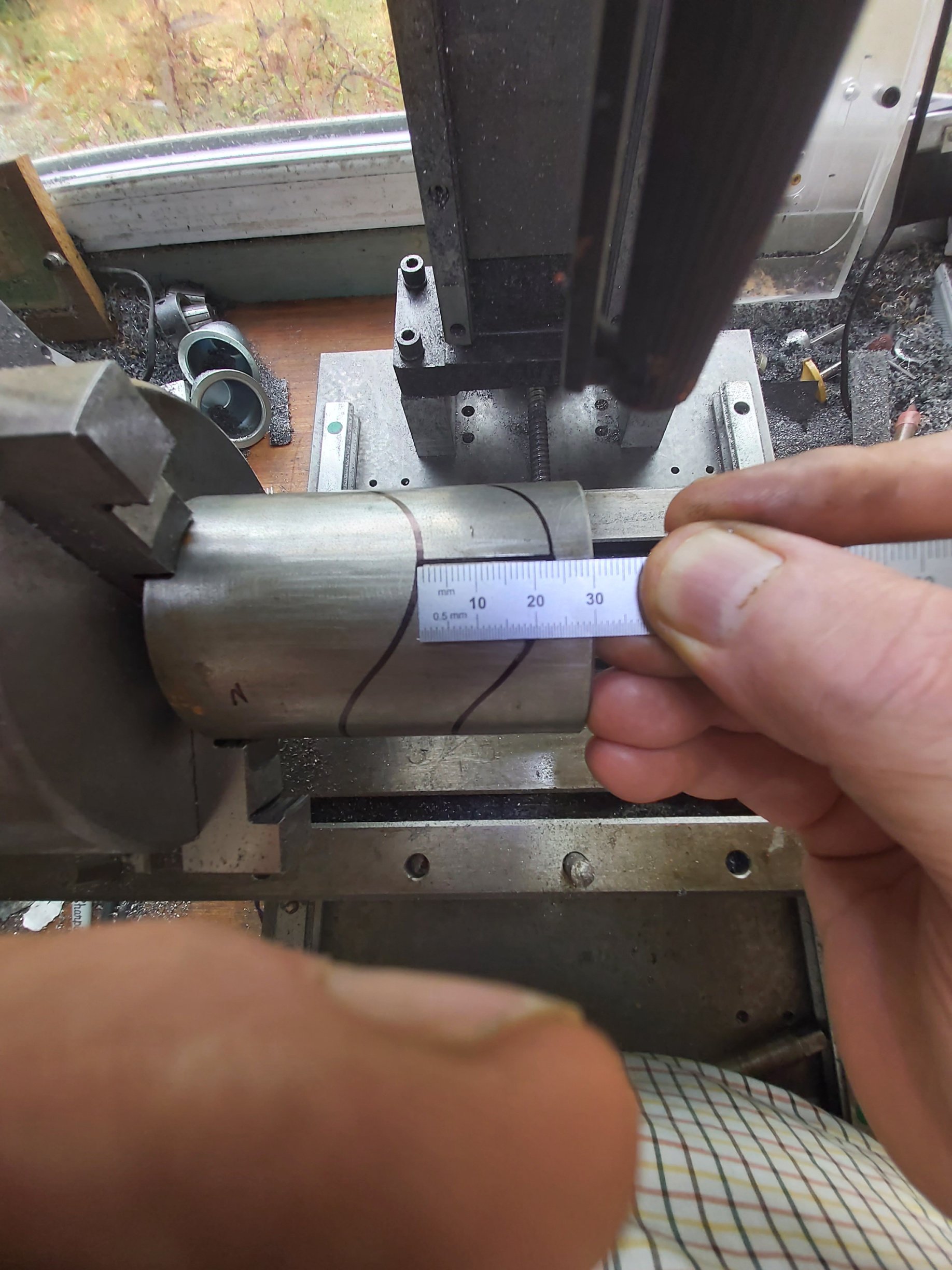
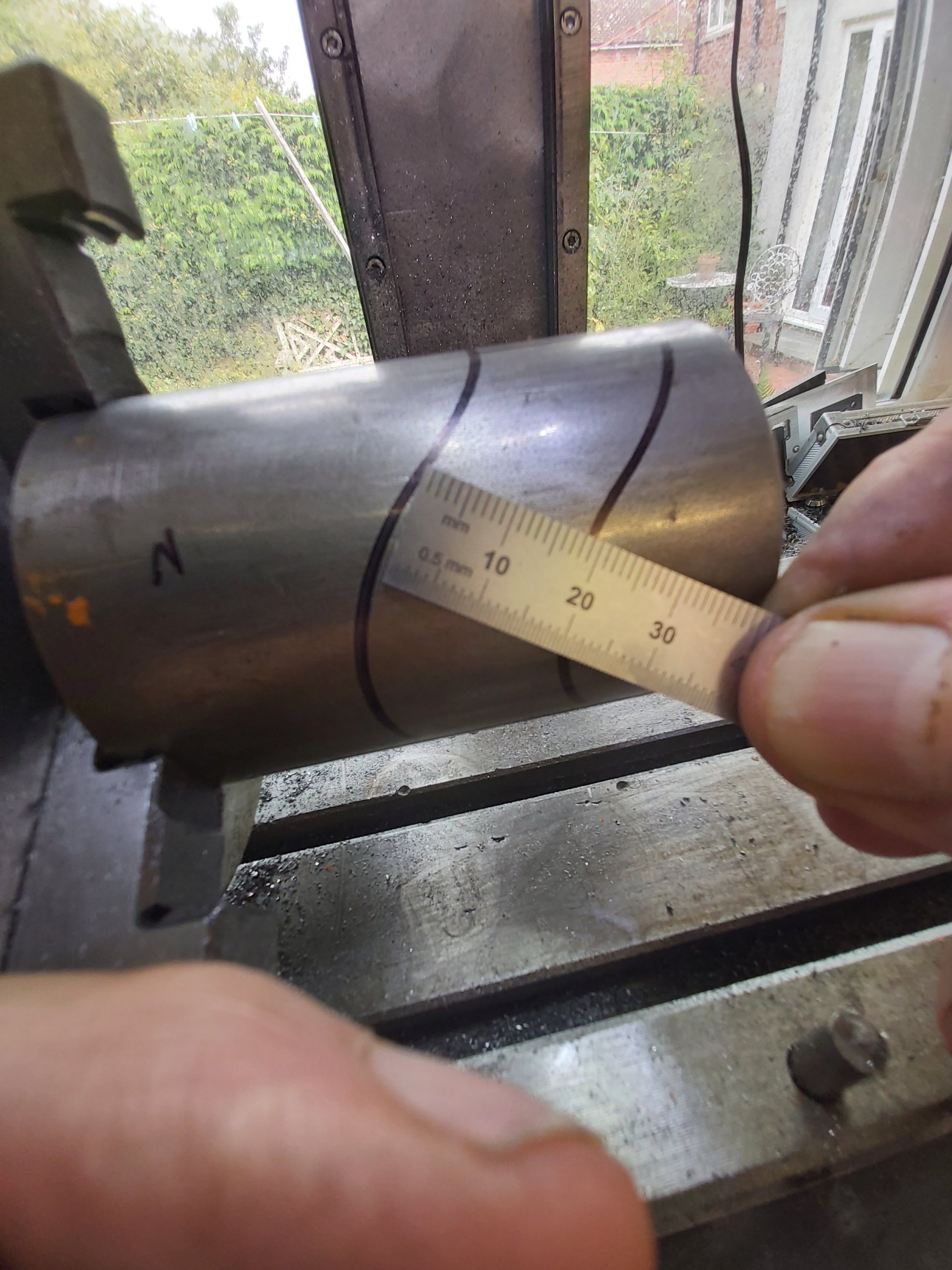
Before starting my cut, I thought it would be prudent to run a pen trace in the mill on the surface of the cam to check the geometry. Here are the results:
And there's my problem. The pen trace 'necks in' between the cusps of the curves. This would be useless for a cam groove, as the follower would just jam up.
Which bit of mathematics relating to the projection of a curve onto a cylinder have I violated? How can I correctly model the curve in OnShape to do what I want it to do? Thanks in advance for helpful suggestions! I've spent 3 weeks banging my head against a wall trying to beat this.


Comments
Personally I like finding solutions to problems like these that avoid the need for the end user to delve into the math. Here's a prior discussion from the forums about how to model this kind of cam follower geometry in 3d. To get a flattened state of the geometry you'd just need to add a split to the cylinder face and flatten to get your slot profiles.
Derek Van Allen | Engineering Consultant | Meddler