Welcome to the Onshape forum! Ask questions and join in the discussions about everything Onshape.
First time visiting? Here are some places to start:- Looking for a certain topic? Check out the categories filter or use Search (upper right).
- Need support? Ask a question to our Community Support category.
- Please submit support tickets for bugs but you can request improvements in the Product Feedback category.
- Be respectful, on topic and if you see a problem, Flag it.
If you would like to contact our Community Manager personally, feel free to send a private message or an email.
How to wrap Lead screw threading around a disc to make a gear.
 hayden_plunkett311
Member Posts: 5 ✭
hayden_plunkett311
Member Posts: 5 ✭
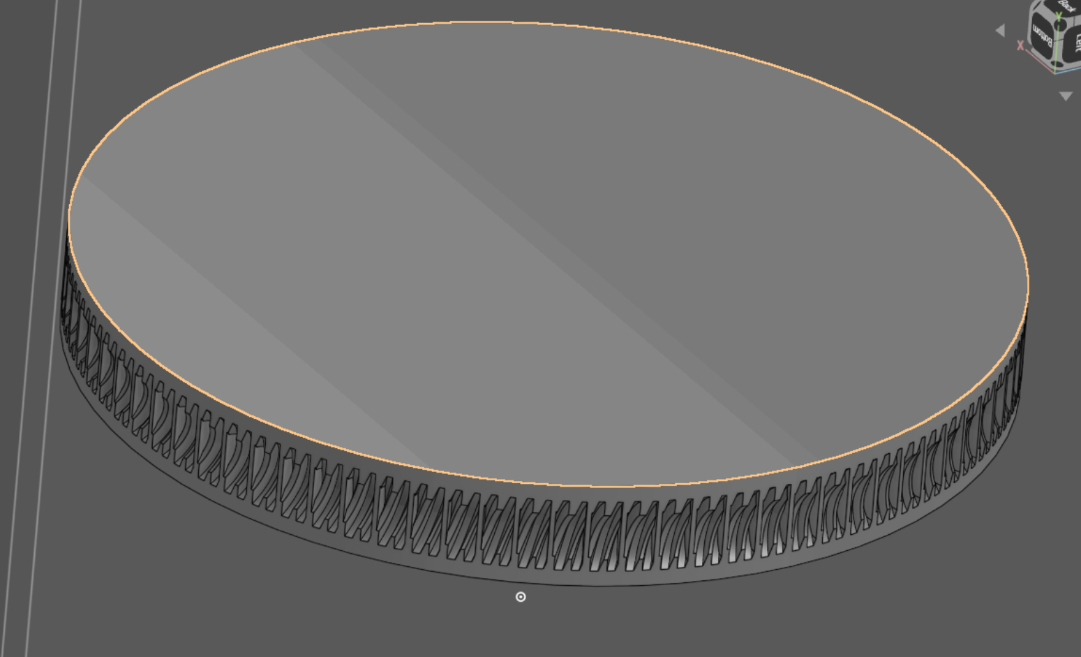
I am trying to make a gear that will mesh with a lead screw, and struggling with how to wrap it around a surface so that it curves around the screw to make the meshing stronger.
I modeled the lead screw to the pitch I have, then created a disc so that overlaps the edge of the screw. Split the screw with planes so its just a few threads, used Boolean remove with a small offset to create the indentation in the disc, then used circular feature pattern to replicate it around the disc edge. No matter how much i fine tune the count of the pattern, the legth of the tool split, I can't get it to be continuous. Advice anyone? Probably going about this all wrong.
Below is what I have:
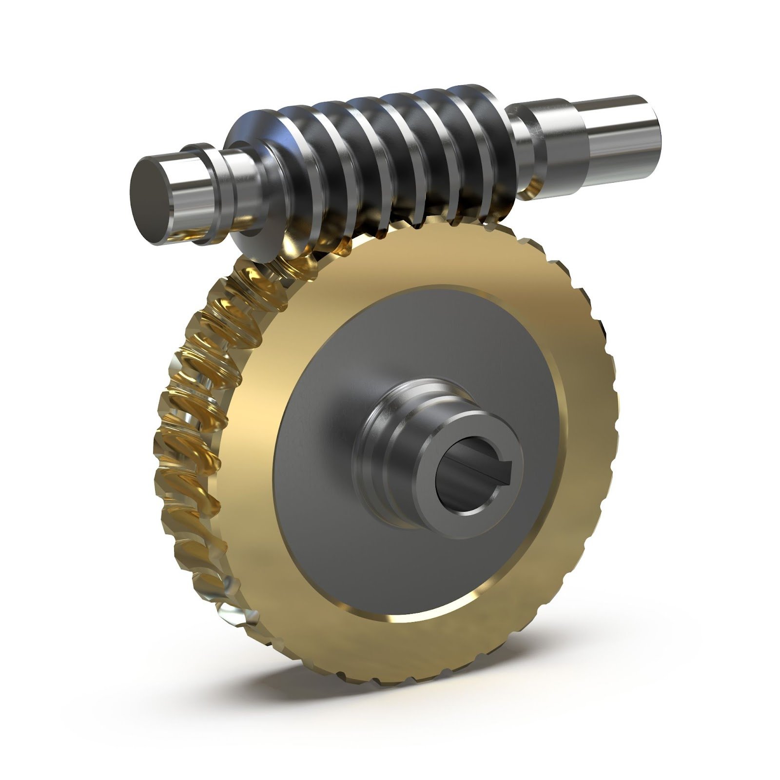
Essentially trying to model this concept, note the inward curve of the teeth of the circular gear. The lead screw i have is a 4 start thread, so not as easy as just making straight teeth:
Answers
I'm afraid that'd be a job for a worm gear feature script. Older discussion may have a hint on what to try: https://forum.onshape.com/discussion/comment/113239#Comment_113239
Looks to me like you might have to circular pattern your lead screw for a count of 3 prior to Boolean. Or just full circle circular pattern remove the lead screw and skip the Boolean. Hard to say without seeing the document or what the If your lead screw looks like before the cut. It almost appears as though the screw is not even a full thread worth long. Also possible may need to enter some math formula in the pattern feature to get it to work out perfectly.
Because the angle changes continually, you cannot just boolean-pattern an intersection around the wheel. The volume needs to incorporate all possible angles of both partners, not just a few.
https://cad.onshape.com/documents/8debf48a92e4eff2ad42217d/w/a8176d7619e9aff1cac8d3e6/e/759a81c91a3ea81b07e15c8f
Thinking of it, I could imagine a FS that relies on the constraints applied and while animating the relationship, creates a boolean every given increment, to achieve a good-enough approximation.
Circular patterns most likely not that accurate. I hope not to imply that.Boolean with offset might get the OP a working draft for proof of concept. Wouldn't know that without knowing the full scope of the project. It looks like OP might just need to get through a modeling challenge without complicating it with "correctness"
Thanks for the input, I kind of figured there was some math, but also constraints within the circular pattern tool that it creates an error w when the indented part of the thread crosses before the outside surface of the disc, hence the gaps.
I'll look into the feature script.
Yes, much of is also me learning conceptually how to do this, then I can increase tolerances to allow things to mesh acceptably with a printed gear.
Martin, that's kind of what I gathered, that the angle of the entry point of a tooth needs to be accommodated. How to model that is the struggle, haha. Still pretty new to all this. Thanks for the visual.
When I'm not away from my computer I can link the document so the tool can be seen.