Welcome to the Onshape forum! Ask questions and join in the discussions about everything Onshape.
First time visiting? Here are some places to start:- Looking for a certain topic? Check out the categories filter or use Search (upper right).
- Need support? Ask a question to our Community Support category.
- Please submit support tickets for bugs but you can request improvements in the Product Feedback category.
- Be respectful, on topic and if you see a problem, Flag it.
If you would like to contact our Community Manager personally, feel free to send a private message or an email.
Help designing an open to closed loft with no obvious planes
 richard_kovanov
Member Posts: 9 ✭
richard_kovanov
Member Posts: 9 ✭
Hi there! I'm new to onshape, and especially new to surface modelling.
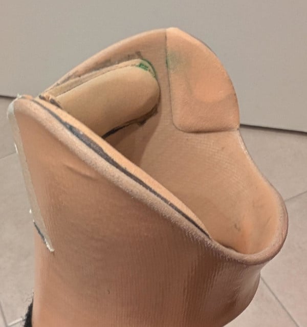
I've watched many videos on the topic and read some threads here, but I'm not managing to come up with a way to design an object like this (it's the top of an orthosis):
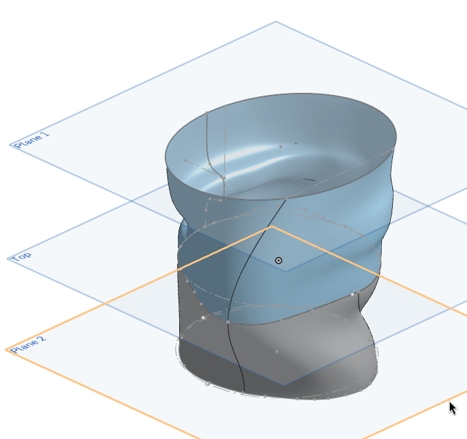
The complexity is that I can't find obvious "planes" I can use for cross-sections. What I tried was 3 ellipsis + guided loft like this:
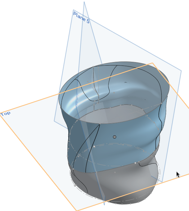
Followed by some awkward planes where I drew some sketches to cut the faces with:
And then I can delete them and end up with something like:
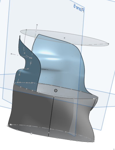
This is not terrible, but it's more art than science (especially the way the sketch planes project to the faces), so I don't feel like I can really control how to cut those faces and merge the open area with the closed one. The curves on the real object are way smoother.
Any suggestions on better ways to try to design objects like this?
Comments
You are in a situation most find themselves in when starting surface modeling. It usually takes a lot of practise and then quite some helper geometry, if you need precise parameters. In this case, EG for the top end, you might want to try looking into the "projected curves" tool, that's the one that looks like a flying pancake: It will give you things like the upper curve all way around in 3D, and in a straightforward and controllable way, at that:
https://cad.onshape.com/documents/ca1999012c8f8157ad62d9c6/w/bfb4e68fbfd9f99849b5b14a/e/058fecc1d6e4413f61ef0e68?renderMode=0&uiState=68ba9cf4867a1f952b42115bThe model is simplified to save a bit time, but you get the idea. Note that curves in the projected sketch planes need to match, and the guide curves need to "pierce" the profile curves by conditions set. Play around with the model to see what happens when you change one thing at a time …
That's amazing! Thanks so much!
Hey, I'm back with another basic question.
I've been playing a bit with this, but lofting is being a challenge mostly because the cross-sections I want to loft with are based on more complex forms (e.g. 3 intersecting ellipsis + fillets). This means the cross-sections have multiple parts, and it's hard to match those parts to the curve parts (which is basically 2).
I tried adding some guides and sometimes they help, but it feels kinda random on when it works, because it's pretty easy to inadvertently create a self-intersecting area.
One idea would be project all the points where splits happen on the cross-sections to the curve, and perhaps add guides on each of them.. but I'm not sure; that also sounds complicated.
Perhaps there's a way to merge the cross-section parts (they're all tangent) and then split them only for the loft (so I could split all entities into 2 or 4 basic points where the guides will be for example)?
Any ideas?
You're making it too complicated. Think bigger and invent the areas you don't need, so you have a simpler shape and someting to cut away later. And yes, the guides need to be exactly on the points on the profiles, of course. Mind sharing the file?
Thanks for the hint. Of course: https://cad.onshape.com/documents/104819752f17568d3a5743f9/w/422e4cc691f082fba43567c3/e/0a14f2589178efc897b8ccf3?renderMode=0&uiState=68c42edba0e3333c11ca0b89Error
I tried to follow your idea and instead of lofting from the surface to a complex area, now I'm just lofting from the surface to a simple curve (which somewhat works).
But I need an additional "channel" where my (small) heel can follow to kinda "screw" in place. I tried to do it like the shared file (the heel channel needs some profile guides, but I can work on this later).
https://cad.onshape.com/documents/175d89821e40bcfa31aebfa8/w/36299cdd8ac686a212dc16df/e/0eb9c1447df4ba44a7f3c0ea?renderMode=0&uiState=68c81023246f765cdbe01dc7
Sometimes, instead of saving the whole world in one go, it is easier to build a general shape, neglecting all the gaps and bumps, then take away areas not needed and create details one by one. This is just one oversimplified sample, but at least it shows a manageable approach. In this case, for example, the 'step' can be edited by simply dragging a few sketch points around, and it probably won't break easy. The same goes for the cutouts: They all live on separate sktches, and can be easily accessed.
Mind sending a new link, please?
Strange. I made three documents public today, and all of them weren't public any more just now.
I've reset it. Try again:
https://cad.onshape.com/documents/175d89821e40bcfa31aebfa8/w/36299cdd8ac686a212dc16df/e/0eb9c1447df4ba44a7f3c0ea?renderMode=0&uiState=68c85645edd463e9a5e38a48
Thanks! I had never heard about Mutual trim, this simplifies everything!
Mutual trim is in fact but one of the powerful tools. When you're trying to take on projects like this, it might prove helpful to go though the surface modelling learning section first. That'll save you a lot of time on your journey down that road.