Welcome to the Onshape forum! Ask questions and join in the discussions about everything Onshape.
First time visiting? Here are some places to start:- Looking for a certain topic? Check out the categories filter or use Search (upper right).
- Need support? Ask a question to our Community Support category.
- Please submit support tickets for bugs but you can request improvements in the Product Feedback category.
- Be respectful, on topic and if you see a problem, Flag it.
If you would like to contact our Community Manager personally, feel free to send a private message or an email.
Problem with patterning an extrude cut hole around a conical sheet metal part.
 DMark_Mark
Member Posts: 4 ✭
DMark_Mark
Member Posts: 4 ✭
Hello
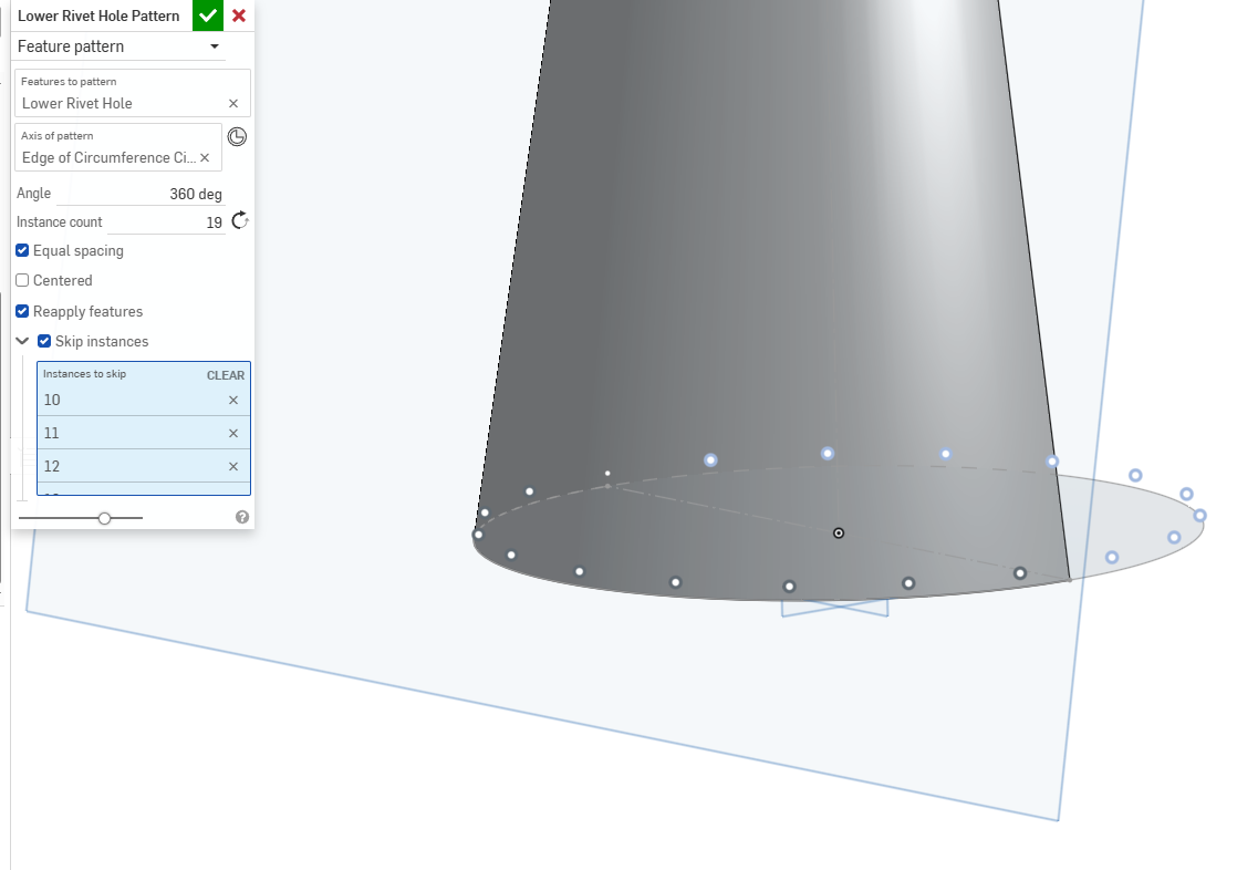
I have a part which I am working on. It is 2 pieces of 1.2mm mild steel which will be welded together to form a cone. It has various holes running around the top and bottom for rivets which will be laser cut into the flattened pieces. I want to make sure that the holes are dimensionally accurate on the 2D drawing/DXF I take from my model, I have managed to add the holes to my model by drawing a plane parallel to the edge of my cone, allowing me to extrude cut a hole perpendicular to the cone and then circular pattern (this was before I converted to sheet metal). But due to this method these are slightly off and are not perfect circles on the sheet metal part when flattened. They would probably be close enough but I'd like to get them exact.
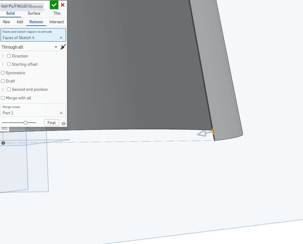
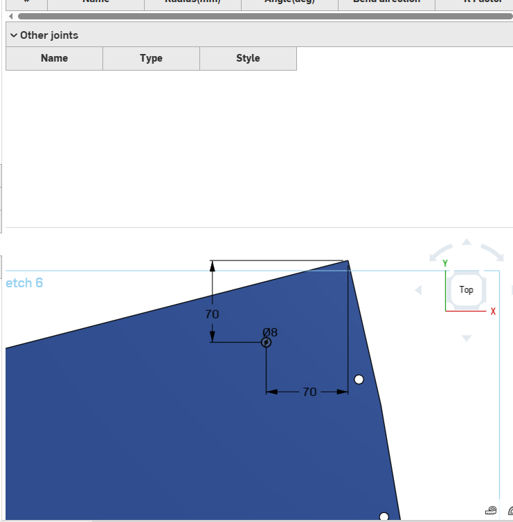
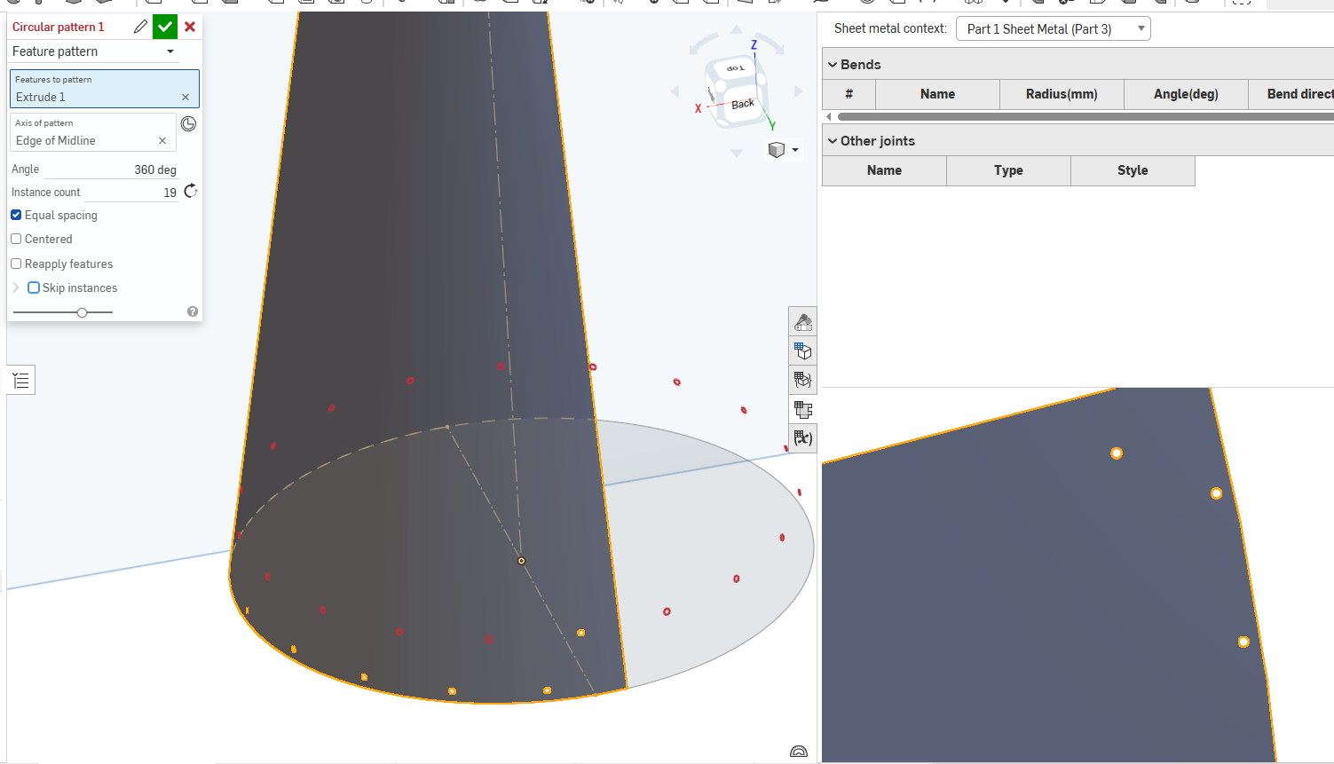
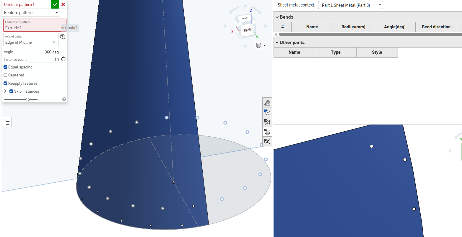
I have been trying to draw a circle on the 2D view of my sheet metal part before extrude cutting it and then performing a circular pattern around the part to copy the hole around with the correct spacing. However I cannot get the feature to work. have tried different settings in the pattern but still no luck. I am new to sheet metal, so am unsure if I am just doing it wrong, but I can't understand why it wont let me pattern the feature. Any help is much appreciated. The image I have attached showing me trying this isn't the exact location of what I am trying to do, simply me illustrating the problem I am having. Hopefully this makes sense, have never used the forums before so am not used to describing a specific problem I am having!
Original Method:
What I am trying to do now:
I look forward to hopefully solving the issue!
Answers
This is one of those specific cases where a sketch pattern might be needed. Usually recommend feature/part patterns but they don't play nice with sheet metal for some reason.
The holes not being round in the flat is due to the sheet metal engine doing the projections from the inside face and outside face and making sure that your cylinder through cut doesn't have any interferences with the metal. Technically speaking, the obround holes generated are correct in the deformed cone state and only look weird in the flat. It's more obvious if you draw an example part with a much larger circular cut through the cone and use a much thicker sheet thickness to see what the flat pattern is doing and why.
Does this matter for rivet holes? Probably not. But it definitely matters if you're gonna punch a hole for a 4" pipe through the wall of the cone.
Derek Van Allen | Engineering Consultant | MeddlerJust a follow up here after a discussion with Derek, You can punch a hole in a cone or cylinder while in the sheetmetal mode and then circular pattern it. But that will create beans (as Derek describes) in the flat metal part. It probably doesn't matter which way its done unless it matters for machine code for cutting out the flat pattern…. then the perfectly round holes may be needed (via sketch and sketch pattern on the flat pattern) depending on how individual machines might interpret the export.
Thank you all for these helpful responses. I thought I had replied last week but I completely forgot! The explanations were really helpful, especially the part about the obround holes generated being correct for when the cone is folded into shape. I'm pretty happy with what I have now. Thanks again!😁