Welcome to the Onshape forum! Ask questions and join in the discussions about everything Onshape.
First time visiting? Here are some places to start:- Looking for a certain topic? Check out the categories filter or use Search (upper right).
- Need support? Ask a question to our Community Support category.
- Please submit support tickets for bugs but you can request improvements in the Product Feedback category.
- Be respectful, on topic and if you see a problem, Flag it.
If you would like to contact our Community Manager personally, feel free to send a private message or an email.
Counterbored AND countersunk holes
 martin_kopplow
Member Posts: 1,309 PRO
martin_kopplow
Member Posts: 1,309 PRO
I wonder how you all handle this type of countersink:
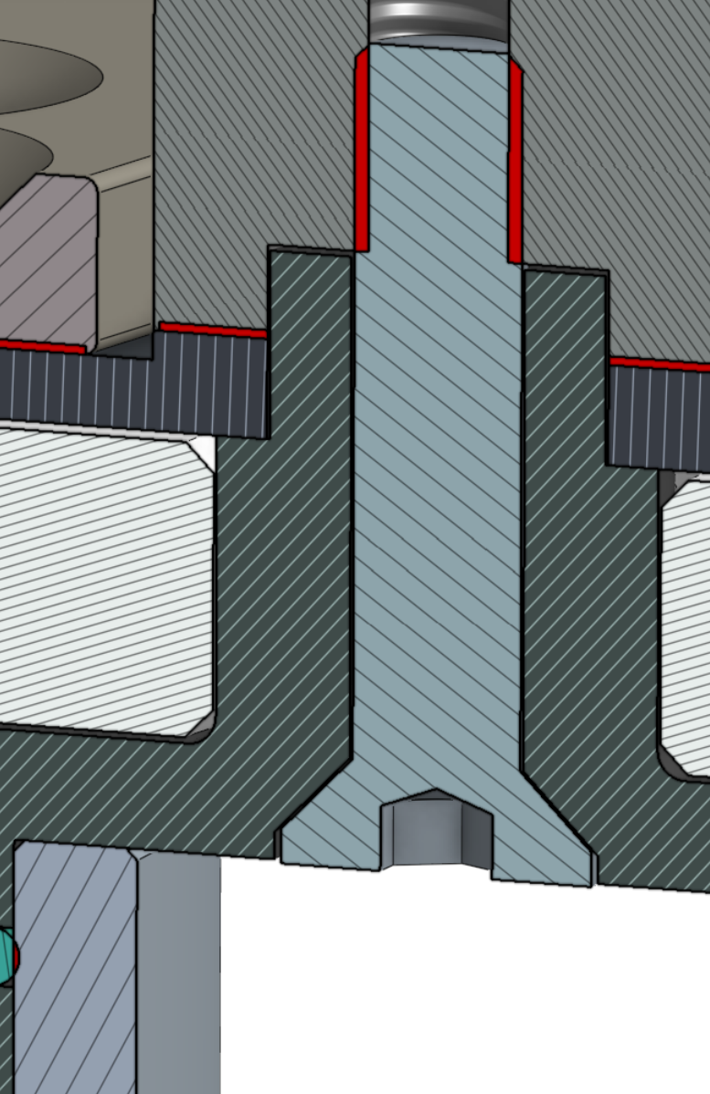
It is a combination of the standard countersink and a small amount of counterbore. I makes sense in cases with little space at the surface, for visually pleasant appearance, or if the screws need to be recessed deeper for other reasons. Pretty common after all.
If modified manually, such holes don't get proper hole callouts in drawings, though:
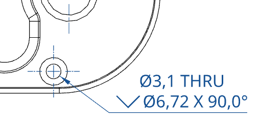
What's the best method to deal with this (except for improving the hole tool), so there are no misunderstandings triggered by actually reading the drawing?
Comments
Is that a "standard" machined feature that would be notated on a drawing with C-SINK or C-BORE (or their symbols)? I think something that specific would demand a cross sectional view with dimensions. The machinist is also at the mercy of the countersink OD he is using to form the step.
It is common, though probably not fully standard, even if it uses all standard (ISO) elements. In this case, for an M4 countersunk screw, which has a 5.6 diameter head (as per ISO), the machinist would typically use a 6mm diam. countersink bit to achieve the desired result. These bits come in all diameters and a pro shop is expected to have at least the common ones. So what he needs to know is how deep the cylindrical part is to be.
This was a simple example. The case would be much more difficult, if we were talking design of injection molded enclosures where the counterbore part might be deeper than the screw itself:
Such holes were possible in my former CAD, even in drawings and callouts. They just require a combination of the counterbore and the countersink symbol, which would be fully consistent, if the hole tool allowed the use of both counterbore AND countersink on the same hole in one go.
A quick search found this example in the literature:
In PTC Creo beginner's tutorial:
And a definition on an older printed DIN standard book page:
So, the latter one proves that it is a standard, at least in the metric world.
I've had clients who want this too and have done enough digging to know it's possible to do with a featurescript, including tagging the geometry with the correct hole callout for drawings, but I'm not aware of an existing feature for it.
The Onsherpa | Reach peak Onshape productivity
www.theonsherpa.com