Welcome to the Onshape forum! Ask questions and join in the discussions about everything Onshape.
First time visiting? Here are some places to start:- Looking for a certain topic? Check out the categories filter or use Search (upper right).
- Need support? Ask a question to our Community Support category.
- Please submit support tickets for bugs but you can request improvements in the Product Feedback category.
- Be respectful, on topic and if you see a problem, Flag it.
If you would like to contact our Community Manager personally, feel free to send a private message or an email.
New User. How do I snap a sketch to an existing sketch element in order to extrude and remove?
 anthony_wilson578
Member Posts: 7 ✭
anthony_wilson578
Member Posts: 7 ✭
Hey all, just picked up Onshape3d today after only playing with Tinkercad or Orcaslicer. My end-use is ultimately 3dprinting keyboard gear and game controllers using keyboard switches- specifically Cherry MX types.
I have found that I was able to import a DXF file for my layout, and extrude the 14mm square holes/footprints (with added recess on the sides for the switches to be disassembled for maintenance without removal) for the desired switches perfectly, but as I am making the walls of my model 5mm thick for strength, I need to add a recess on the back side so that the switch itself only has 1.5mm of thickness in it's immediate surroundings for proper snap-in. To this end I believe that a recess of about 18mm square and 3.5mm deep will be plenty on the underside of the top plate.
My understanding is that i need to sketch an 18mm square shape, rotate it 10 degrees, lay it on the face, and then extrude this to remove material. I am struggling with finding the proper workflow in order to do this. I am new to real CAD/3D modeling so I am out of my wits.
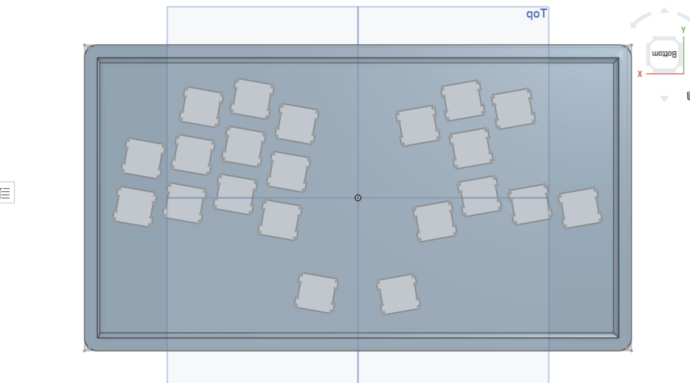
I've attached some pics of the model.
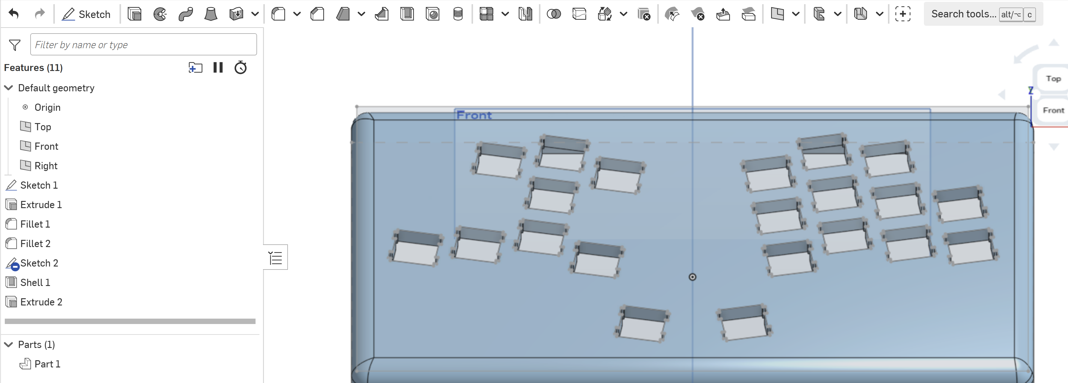
Here's the view from the underside, for reference, this is the face where the recesses need to go, centered on each opening.
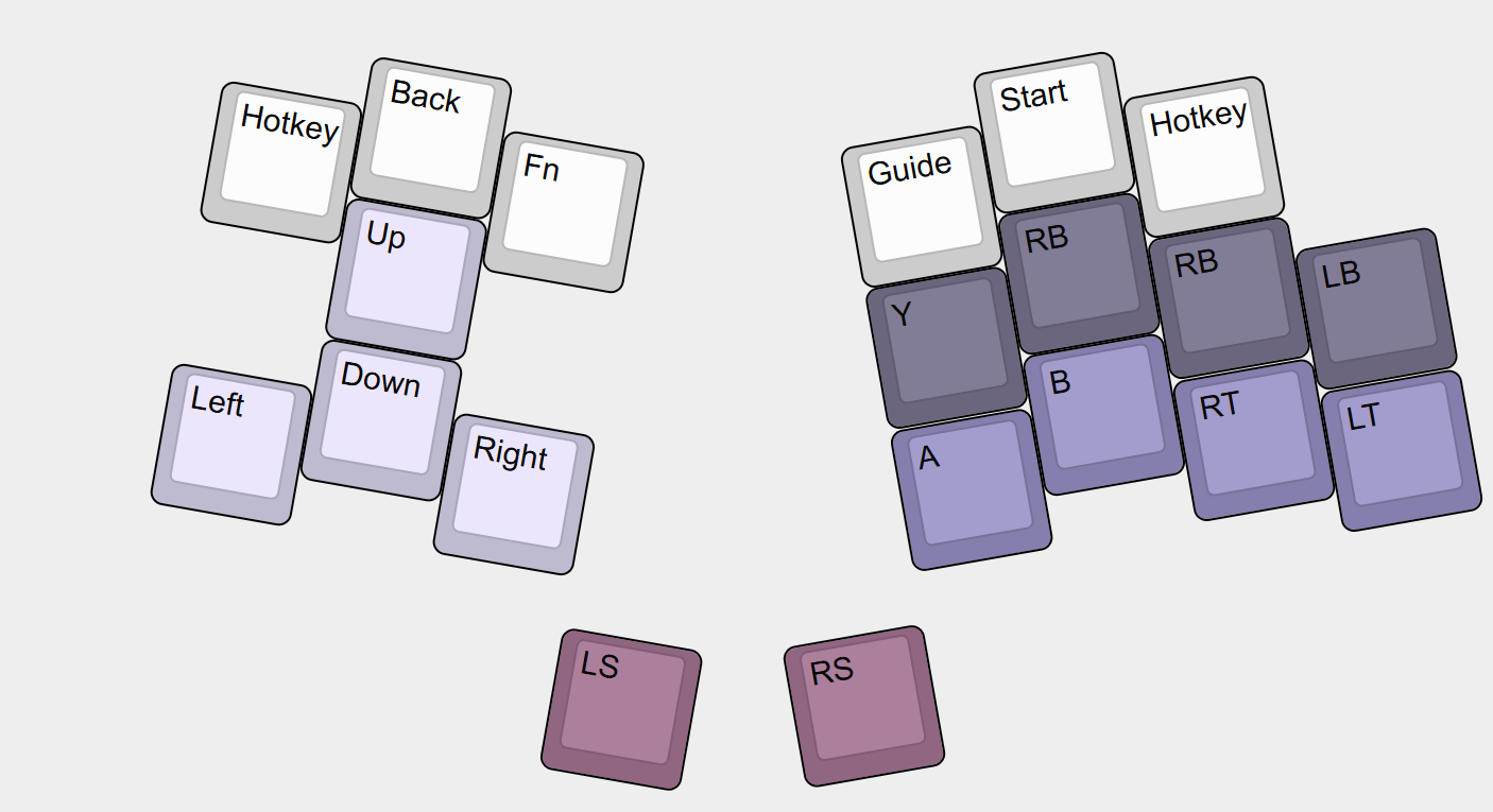
Here's the keyboard layout, missing one key to the left (I am adding it for better symmetry and for a shortcut/function/macro feature) for those interested. This will be for general PC gaming using aRaspberry Pi Pico running GP2040-CE game controller firmware.
Please let me know what my next steps are.
Comments
Here's my advice:
First make sure you get one key+hole dialed in on a tiny board. (both in CAD and with 3d print prototyping) this will speed up your iterations and make for a better design.
Then use linear pattern or transform patterns to get the proper key layout with that perfected hole.
Patterning in sketches works, but isn't ideal ususally.
I've already vetted that this footprint and recess works well via a physical 3dprint.
Hello Anthony. How did you arrive at your current sketch? Did you use a sketch pattern? - Scotty
I think that importing a sketch just to help with the layout makes more sense here, and then doing linear/transform patterns to actually model the cutouts. A rather advanced choice of first project! I will play with it some more.
The physical body I started by drawing a rectangle and extruding, filleting, etc. The actual DXF file I was usin was generated by a custom keyboard site- you build a layout and then copy/paste the JSON file to spit out an SVG, STL, or DXF file that can be imported into CAD or laser cutter services.
This to generate the layout, and create the JSON-
https://www.keyboard-layout-editor.com/#/gists/f7e7fa6e7b40bc909a8d6cdebf5a4828
This to spit out the the SVG/STL/DXF
https://www.keyboardcad.com/
I think maybe I can try an STL followed by import by 3d file maybe?
In the meantime I am playing with getting used to design geometry for the chassis, and it's a good skill building exercise.
What I think will work for you without a lot of work is:
On the underside face create a sketch and with the Use tool, capture the sketch elements of the key openings of the top side. For each key opening, draw a diagonal construction line from one corner to the opposite corner of the key opening sketch elements and put a point at the line's center.
Sketch a center point rectangle at the center point of the construction line (any one of the center points) you created using the dimensions you want. Use Transform to get the orientation correct.
Use Extrude Thin to create the support walls.
There is a custom feature script called Point Pattern. With it you can copy that 'wall surround' to any points.
Check out this document. Perhaps you can make use of that feature script. - Scotty