Welcome to the Onshape forum! Ask questions and join in the discussions about everything Onshape.
First time visiting? Here are some places to start:- Looking for a certain topic? Check out the categories filter or use Search (upper right).
- Need support? Ask a question to our Community Support category.
- Please submit support tickets for bugs but you can request improvements in the Product Feedback category.
- Be respectful, on topic and if you see a problem, Flag it.
If you would like to contact our Community Manager personally, feel free to send a private message or an email.
Fusion to Onshape: Using a part to make a cut in other parts
 troy_ostrander
Member Posts: 77 ✭✭
troy_ostrander
Member Posts: 77 ✭✭
How would you translate this task to Onshape.
For example: In cabinet making > Use fastener geometry to cut into another geometry to make space for it.
Keep in mind I am used to Fusion's hybrid modeling environment where there isn't a Part and Assembly studio. In Fusion parts and assemblies in can be one file. I understand the Part and Assembly environment but I am curious about best practices in Onshape as it pertains to this task.
doc link: https://cad.onshape.com/documents/811f3461d10875305845b120/w/39c111e200b461fcc4ae0722/e/bfb502bea0f57b90dd506c0a
See video demo link here:
Comments
If the solution is to "create part studio in context" and do the Boolean Subtract there. I still don't understand how.
See demo video link:
@troy_ostrander
That would be one way to do it. In Onshape, things tend to get a bit more strategic than in Fusion. The question is what part carries the information of the position of the fasteners. Maybe it's the lateral part, in this case. Let's assume this.
If I was to do it, I had a part (or even a little assembly) in some document, representing the fastener (and all it's configurations). I'd keep that in a place where I have all my fasteners. I'd then make my lateral element in a part studio inside some other document, maybe where the cabinet assembly also lives (And I would certainly NOT delete the default planes and hide the origin, but rather USE them!). If I wanted to use the fastener as a tool for a boolean, I'd "derive" the fastener into my lateral element part studio, position it, and do the boolean there, and only once, then pattern the cutout along the edge (in case I need more than one fastener) or even mirror it over to the opposite edge. I'd then have my lateral element complete, ready to assemble.
Only in the assembly would the 'real' fastener and the door ever meet. The fun part is that once I have all the cutouts in my part, and positioned one of the fasteners, there is the "Replicate" feature, available in assembies, which will automatically put as many fasteners in my door as I have made cutouts. Even If I decide to make more cutouts after the fact, it will populate these with the appropriate number of fasteners.
Thanks @martin_kopplow, OK We're getting somewhere. The "in context" is out for now. I am using "Super derive" and Boolean Subtract to make room for fasteners.
It's pretty straightforward my only question now is how do I sync the configuration of hardware used for subtraction with the hardware inserted in the Main Assembly?
There must be a clever way to do this.
Demo video link:
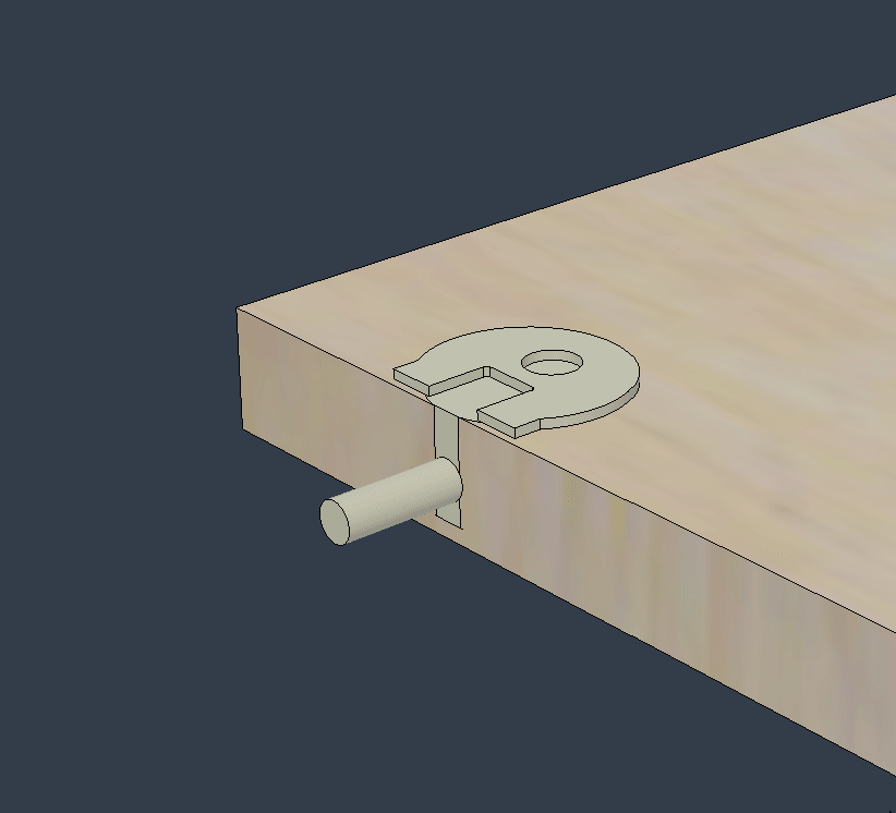
Quick gross example of cabinet hardware I pulled from McMaster Carr and lazily slapped together with bad positioning but just to prove the concept. The same philosophy of using Super Derive or Point Derive led me to developing my custom Amalgamate feature which has the advantage of allowing you to pre-define which tool bodies are meant for subtraction operations or union operations in the seed part studio, as well as letting you do both subtractive and additive operations in the same step.
It has the option to insert the parts from the seed studio right into your part document if you want, or not if you don't want to have a weird BOM with duplicate entries. Here's a demo video of me tagging my subtractive bodies and insertion bodies for this hinge. (No union tools because we're only cutting holes, not adding to the cabinet geometry)
And here's a demo of the Amalgamate feature being applied (I pre-placed mate connectors to make the selection fast enough to fit in a gif)
Derek Van Allen | Engineering Consultant | MeddlerIf you use the insertion function of Amalgamate your inserted parts will always be synced with the geometry that goes with them. Downside is that the BOM will show all of your shelf pins as 1 of 1 so it just comes down to whether or not the BOM details are important to you or if the sync is more important to you. In my industry everything is essentially treated as 1 of 1 BOM items so we don't mind the funky way it reports at the assembly level.
Derek Van Allen | Engineering Consultant | MeddlerIn Context can be powerful, but if used exessively, it'll get out of hand rather sooner than later. The derive approach is more targeted and can be traced back easier than the various levels of contexts of in-context dependencies that may come into existence. I'd only use that to create assembly-driven skeleton geometry, but not details.
You could try Derek's approach. Or, you could derive in two steps:
It all depends on complexity of the fastener model. The above will work if it is simple in a way that has identical geomery for the boolean and the assembly. You could then edit the first derive operation to drive both configurations.
In my case , there would probably be too much detail on the fastener model (I do frequently create renderings off the same assembly) to use it for booleans anyway. I'd resort to deriving it into my part studio as decribed, but instead of doing a boolean, I'd only use certain key geometry (like diameter, depth and centerpoint) to create the cutout, or ideally only position it and then use e.g. a hole feature to remove the material. That way, I can later edit it easily, I get hole tables and hole callouts in my drawings and so on. It depends on what you are after …
For some stuff, I have a detailed model of say the fastener and the same document also holds a simplified model that only defines the volume.
Anyway here's a demo of the above process. I used an external document that hase a configurator to create the fastener I wanted to use/derive. Then I used that for the part studio boolean and also for the assembly. After updating the initial config, both update:
I hope it comes clear. What a pity I cannot upload vids with audio here.
@martin_kopplow for kicks I decided to torture test the amalgamate feature with a part using the worst performing geometry I could think of just to see how it would do. 70+ second rebuild time in the seed studio for a single knurled "bolt" with knurled threads, but with some clever configuring to simplify geometry I can get a build time of ~ .3 seconds to swiss cheese this polyhedron with perfect holes to hold a bunch of them. I also made it so the high detailed version of the studio had the tag feature suppressed just to prevent anyone from actually attempting to use the 70 second rebuild time version of the model for renders as tool geometry. The inner workings of both our methods rely on the same derive architecture in reality, all my feature is doing is wrapping that up into a tighter UI to minimize the number of extra steps you need to take on the import side of things.
Derek Van Allen | Engineering Consultant | MeddlerThanks @Derek_Van_Allen_BD I will keep in mind the Amalgamate feature. This seems like the way "modern" CAD should work . This seems so intuitive to me to just use the hardware to make the substructions no matter where it is: part or assembly. I have to say this is easily done in hybrid modeling in Fusion.
So for now but for now I am going to use sketches to extrude/subtract space for hardware in part studio and configure those subtractions in the part studio…. Then mate the configured hardware in the assembly and also configure them to match the subtractions in the part studio. Crazy to me but lets try it.
I will still be searching for a better way so I am open to any suggestions and I will report back here if I find out anything.
And thanks to @martin_kopplow !