Welcome to the Onshape forum! Ask questions and join in the discussions about everything Onshape.
First time visiting? Here are some places to start:- Looking for a certain topic? Check out the categories filter or use Search (upper right).
- Need support? Ask a question to our Community Support category.
- Please submit support tickets for bugs but you can request improvements in the Product Feedback category.
- Be respectful, on topic and if you see a problem, Flag it.
If you would like to contact our Community Manager personally, feel free to send a private message or an email.
Auxiliary view along 2/3axis of reference defined by a mate connector
 jerome_goyet
Member Posts: 16 ✭✭
jerome_goyet
Member Posts: 16 ✭✭
Hello,
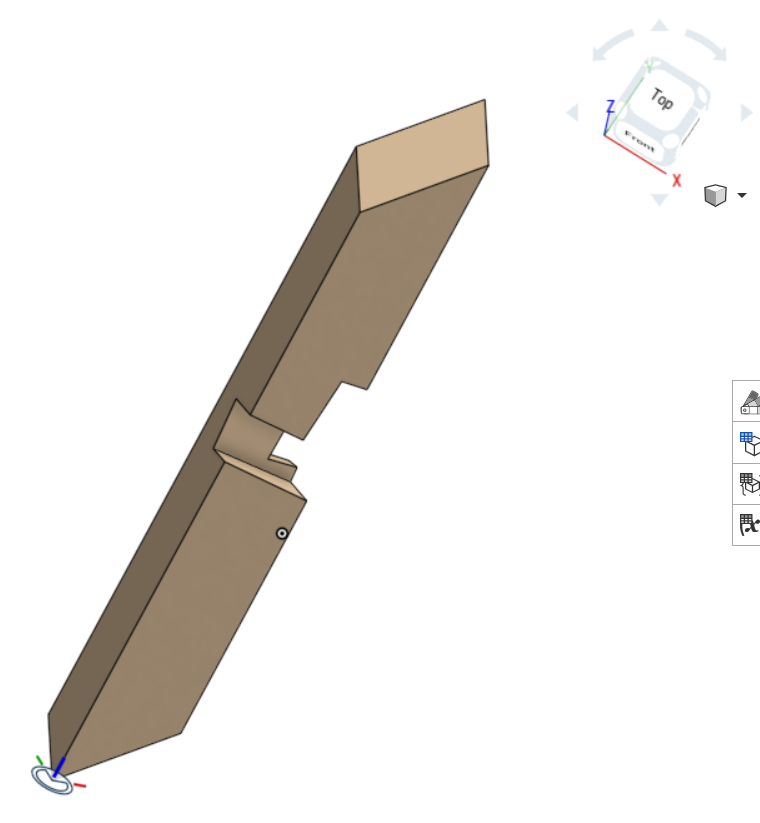
I'm facing an issue to create a drawing of an object (an inclined wood beam with cutouts) whose the 3 axis of reference are not aligned with the reference axis system of the part studio (see illustration below). (https://cad.onshape.com/documents/ebf002a1ff45a52d801e6eed/w/3359f17212fd50a58f7a11c7/e/439f195de9388e3e90acbabc?renderMode=0&uiState=694bc2c3dea6cb1314780a89)
What I need is to create some auxilliary views having the axis of reference definied by the mate connector (see pictures below) . The auxilliary view option of the drawing interface does not seem to be approriate for that (Normal or In line).
Is there any workaround solution or any hidden features in Onshape to allow tracing these drawing views ? (Two possible solutions : to duplicate the part and rotate it along two axis to have it aligned relative to the 3 axis of the part studio or to align it with mate connectors in an assembly and then create a drawing from the assembly…quite a pain)
Many tks
Best Answer
-
 glen_dewsbury
Member Posts: 1,354 PRO
glen_dewsbury
Member Posts: 1,354 PRO
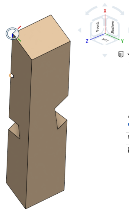
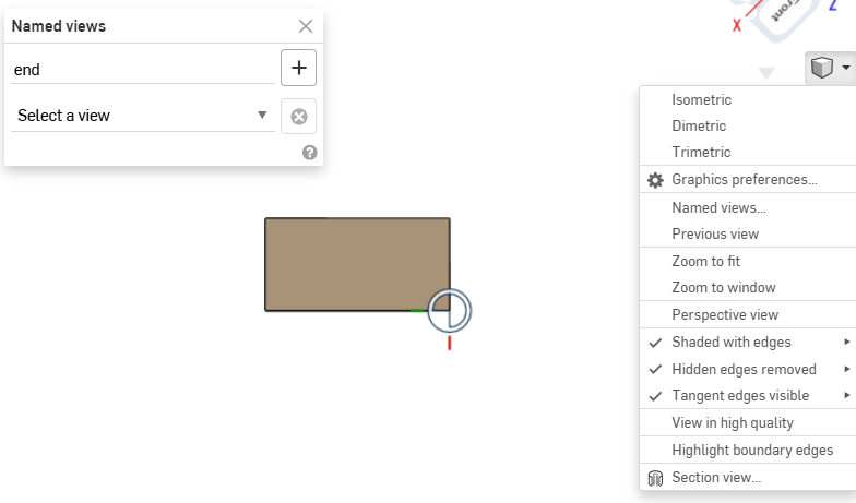
You could use named views for this. I used the mate connecter to set view normal to end then turned it into a named view.
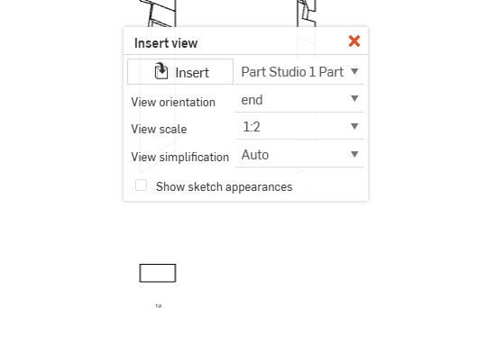
Called up the 'END' view in the drawing to see the end then added auxiliary views.
 0
0
Answers
You could use named views for this. I used the mate connecter to set view normal to end then turned it into a named view.
Called up the 'END' view in the drawing to see the end then added auxiliary views.
https://cad.onshape.com/documents/98659d896b26c7cea1d123c4/w/44ec2798fe67f6bf39367981/e/2cbeb7014f8cbb8e6f51a4d2
Many tks, sounds great, dead easy and answers the need !
Hello Glen,
I've just figured out that your method fullfill my need, however, I found out one drawback : each time you modify the part (eg. its orientation), then you need to save a new view (so far so good). Then, when you open the drawing and update it with the new view reference , all views on this drawing are superimposed and cannot be rearranged properly and are not correclty projected. Any hints to solve that ?
Many tks
Yes, that is true. When you reorient any part in an assembly, however, and then open the drawing which is drawn from that assembly, all views of the part are always no longer aligned as before. That is just the nature of assemblies. To get around this, if possible, always make part drawings from the part studio or (if you need the part together with say fasteners in the part drawing) make suitable subassemblies for the drawings.
Taking this a step further, one could come up with the idea of making view orientations parametric: Say place a mate connector on the part to define the primary and secondary view direction and make that MC selectable in the drawing view menu. That's one for the developers, though.
hello Martin,
you mentioned assemblies, but in my cases I only used the part studio to place my MC to create and save all required views for drawing, It does not work either.
Anyway, tks for your support (your selectable MC in the drawing view would be really valuable)
Hmmmm … interesting approach. I usually never ever reorient parts in my part studios, so I might not see exacly what you see. I usually create the parts in place and should there be more than one, that is obviously because I want them referenced to each other, say by mate connectors or sketches. That helps me keep my history clean. When I edit one part, the part(s) referenced might then of course update, but that's all movement that takes place. For parts that have no references, I usually create a new part studio. Whenever it comes to moving parts around, I usually do that in an assembly.
Have a look at this update. I've added some other views that look cleaner to me. See if this helps. It makes for a vert busy part to detail. Hope this helps to get started.
https://cad.onshape.com/documents/98659d896b26c7cea1d123c4/w/44ec2798fe67f6bf39367981/e/2cbeb7014f8cbb8e6f51a4d2
Martin,
The reason why I only work in the part studio is because the 3 parts are identical (3 table legs), I don't need to create any assembly and above all, I only need to tweak the different angles set as variables to find the best arrangement (see the variables tables in the part studio, i.e. 'torsion', 'inclinaison'…) . Then I need to update the drawing once I've found out a correct set of angles. (hope I'm crystal clear ;-))
Glen,
tks for you update, I'd had a try with your doc. I think the only way to get an updated drawing is to start it from scratch again by saving a new view in the part studio and then insert the part with this new view orientation, meaning that all projected views on initial drawing have to be erased. I'm pretty convinced that Martin's solution would perfectly anwser the need and be really straight forward (Use of MC as reference in the part studio (or assembly) for view orientation in the drawing Insert view tab), I don't know how this solution could be pushed.
Tks to both of you, and hope it may feed all Onshpae improvements thread.