Welcome to the Onshape forum! Ask questions and join in the discussions about everything Onshape.
First time visiting? Here are some places to start:- Looking for a certain topic? Check out the categories filter or use Search (upper right).
- Need support? Ask a question to our Community Support category.
- Please submit support tickets for bugs but you can request improvements in the Product Feedback category.
- Be respectful, on topic and if you see a problem, Flag it.
If you would like to contact our Community Manager personally, feel free to send a private message or an email.
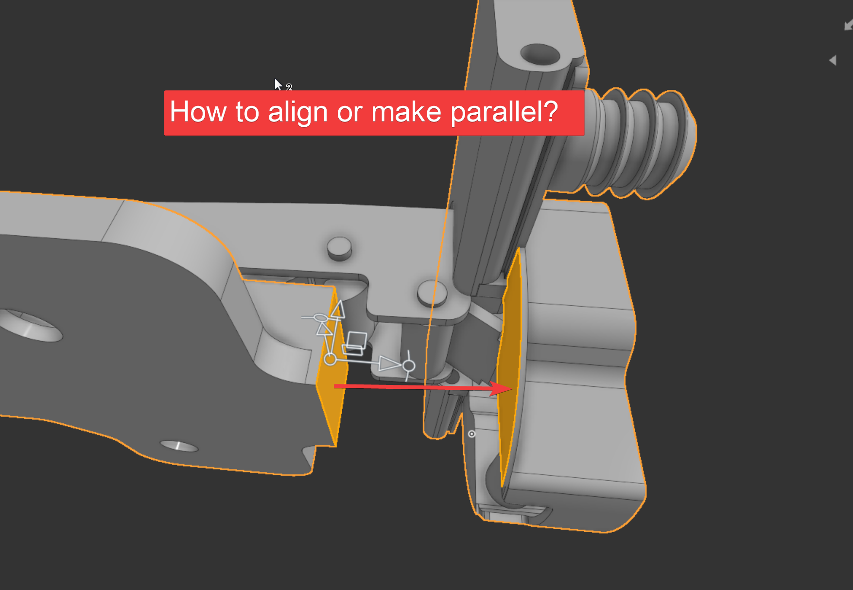
How to Align Or Make Parallel?
 troy_ostrander
Member Posts: 81 ✭✭
troy_ostrander
Member Posts: 81 ✭✭
See Screenshot, video demo and document link.
https://cad.onshape.com/documents/38fdde76101f4fbc9bb58263/w/05725c36720b0fed02c11184/e/2811a064f938e7c6418410ba?configuration=List_9AsU3SuQNOMyge%3Dfree%3BList_Pw7XxggYNiDOYh%3DCopy_of_FO0&renderMode=0&uiState=69538df6764c92608cd973da
Best Answer
-
 martin_kopplow
Member Posts: 1,254 PRO
martin_kopplow
Member Posts: 1,254 PRO
The trick here is not to use the parallel mate on the faces you actually want to see parallel, but on two entities (faces, or ideally MC) which are parallel anyway. That may appear wierd at first glance, but we can then be generous with the parallel offset limits, for that is already taken care of by chosing parallel faces and it controls nothing. Then, we're left with the angular limits, and we use these, set ithem to say 0° and 90° and realign the MCs used so as their secondary axis' are aligned with one of our preferred reference edges each.
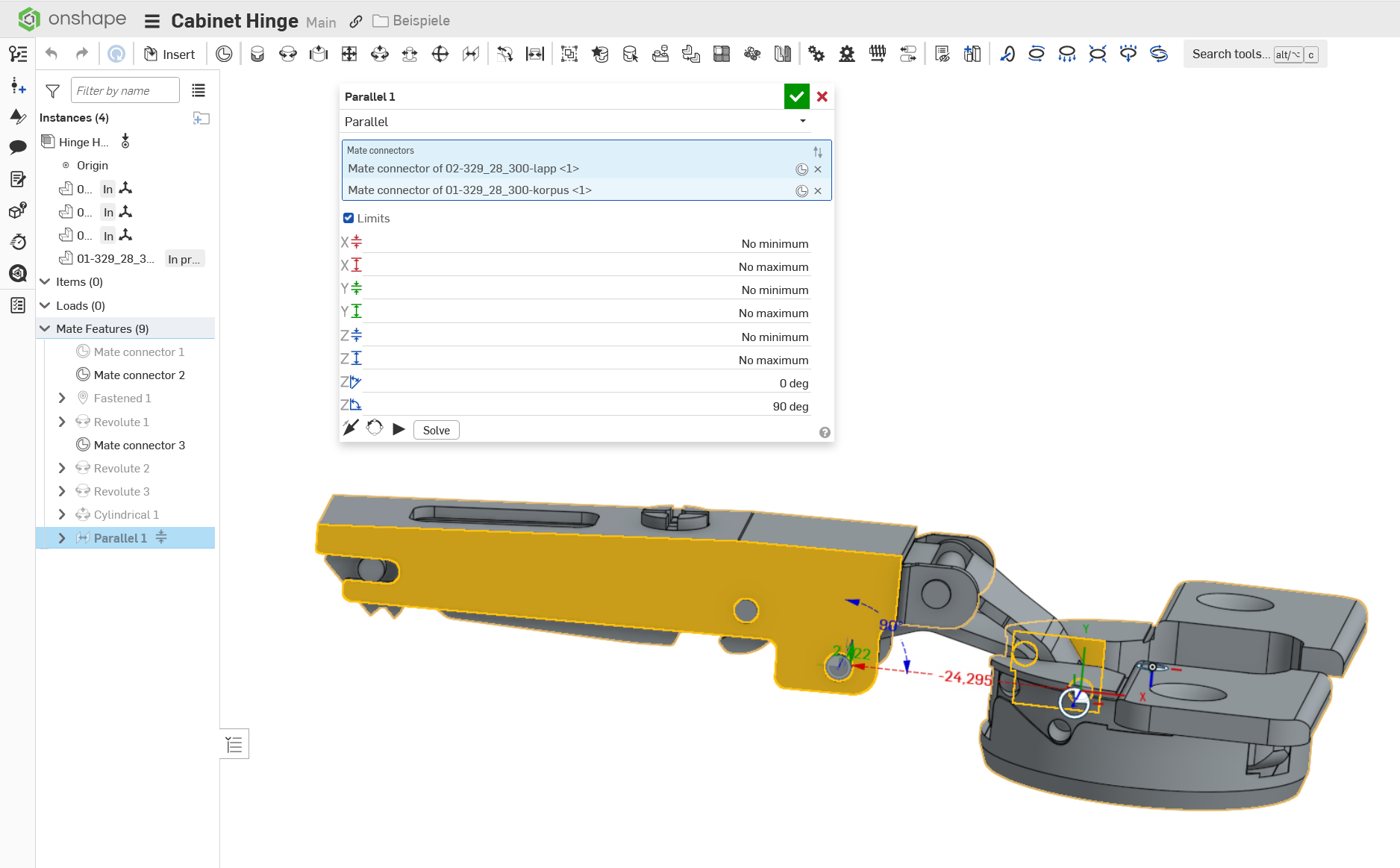
Your model was read only, so I grabbed a similar one from Grabcad and didn't bother to configure it, but you get the idea.
1
Answers
@troy_ostrander
The trick here is not to use the parallel mate on the faces you actually want to see parallel, but on two entities (faces, or ideally MC) which are parallel anyway. That may appear wierd at first glance, but we can then be generous with the parallel offset limits, for that is already taken care of by chosing parallel faces and it controls nothing. Then, we're left with the angular limits, and we use these, set ithem to say 0° and 90° and realign the MCs used so as their secondary axis' are aligned with one of our preferred reference edges each.
https://cad.onshape.com/documents/e1a0d021cb8c992c2b5665a0/w/c32972d508d496134cf0a8c5/e/eeae4fee28b063ae67802481?renderMode=0&uiState=6953d09c418265147167556f
Your model was read only, so I grabbed a similar one from Grabcad and didn't bother to configure it, but you get the idea.
Thank you @martin_kopplow! Here was how I applied you solution. See Screenshot, video demo and exportable link.
https://cad.onshape.com/documents/e1a0d021cb8c992c2b5665a0/w/c32972d508d496134cf0a8c5/e/eeae4fee28b063ae67802481?renderMode=0&uiState=6953d09c418265147167556f
@troy_ostrander
Hihi, you're funny, that's my own link. ;0)
Anyway, I get it. Yes, you may use the angle of the parallel mate for a leaner configuration table. The nice part is that this way you can use one single variable for all the positions required and easily add some variables to drive positions for special conditions or sync them with other hinges, e.g. in case of folding doors of for non-rectangular cabinet.