Welcome to the Onshape forum! Ask questions and join in the discussions about everything Onshape.
First time visiting? Here are some places to start:- Looking for a certain topic? Check out the categories filter or use Search (upper right).
- Need support? Ask a question to our Community Support category.
- Please submit support tickets for bugs but you can request improvements in the Product Feedback category.
- Be respectful, on topic and if you see a problem, Flag it.
If you would like to contact our Community Manager personally, feel free to send a private message or an email.
New Custom Feature: Hole Row
 joshtargo
Member Posts: 575 EDU
joshtargo
Member Posts: 575 EDU
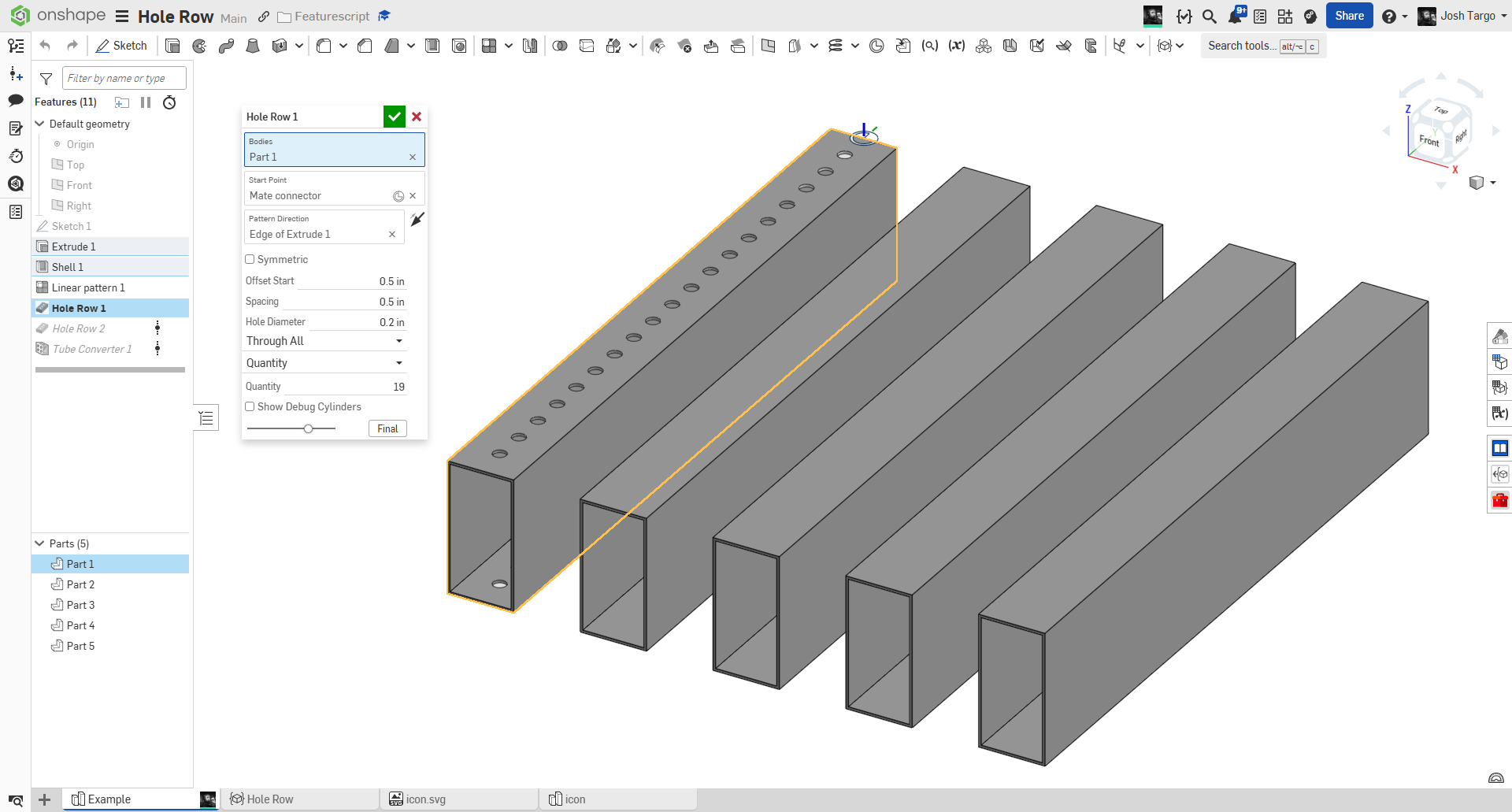
Make a row of holes. Specify depth, diameter, spacing, offset, affected bodies, and symmetry, without a sketch!
Featurescript
https://cad.onshape.com/documents/66ce4c4209c4da7929ad086d/w/4d77fbc41af171917cc4e3b6/e/716e513e17c51868c34d980f
1
Comments
Does this have any functionality that a hole and a linear pattern don't already have?
(Also your document isn't public)
Experts in Onshape Automation - Custom Features and Integrated Applications
@Caden_Armstrong public now. and yes, for my intended use case, my script lets me make a line of holes with one feature, and fewer clicks, at the expense of some functionality that I rarely use. Also, making the line of holes automatically go to the end of the part means it updates if the part changes. I plan on doing something like a second direction, but it will be more of a "clone row" so you can just have multiple rows at multiple MCs.
For our robots, almost 100% of our holes are 0.200" and the majority are spaced 0.5" along a straight line.
I've been meaning to develop the generalized version of this that handles arbitrary face shapes for some time. We draw a lot of weirdo spline geometry that needs a hole pattern up the centerline of the parts, so Flange Warlock will one day come out of the backlog and see the light of day.
Derek Van Allen | Engineering Consultant | Meddler@Derek_Van_Allen_BD do you have an example of what it needs to do?
@joshtargo without showing off anything too proprietary about the construction of some of these projects, here's a sample reservoir section from one of our builds. Most of these table sections have these bolt flanges that are wiggly shapes on the handrail sections and the table segments bolt together with a flange that varies in thickness from the top to the bottom of the part and around the corners. Ideal bolt locations for these connecting flanges would be placed on the exact medial axis curve for the flange. For simple rectangles or paths with a consistent cross section it's no biggie, but variable thickness geometry presents a much more non-trivial problem to be solved.
Specifically these flanges are the challenging ones
Offset curves from one edge or the other are necessarily biased towards their side, so the development of a better medial axis function is the first step. I've done it 3 different ways now without being satisfied enough to publish my methods. Delaunay Triangulation was one route but it's slow. Tween Curve is pretty solid but requires knowledge about edge chains that I'm trying to avoid the user needing to input. There's the rooftop method where you extrude a face with a draft and extract the peak curves and project them back to the face and that's what you see being used here, but it has a lot of failure cases to resolve.
Derek Van Allen | Engineering Consultant | MeddlerI will give this some thought.
are you trying to avoid having the user click edges at all?
Yep. Just click the face and holes pop in magically. Reason being, edge definitions are inherently less stable than faces, and I can do a lot of query magic to try to stabilize the reference but I'd rather just have a script developed that only needs the face to be selected. Also opens the doors for more procedural modeling documents later if the only necessary reference is a face.
Derek Van Allen | Engineering Consultant | Meddleryou specify the first and last hole edge distance? or just a number or spacing of holes?
The medial axis method I'm currently using sort of takes care of the first and last hole distance by placing the hole directly on the end of the curve, which should by definition be equidistant to all of the things at the end it's supposed to be equidistant to. Then the spacing in between would be some flavor of spacing chosen by the user. Maybe the holes need to be precisely 3" apart or maybe it's by number or maybe it's as close as you can get to 3" spacing while maintaining start and end conditions. The hole spacing is the easy part, really. It's the medial curve generation that's been doing my head in because I don't live in a world with nice rectangular profiles or consistent part widths.
Derek Van Allen | Engineering Consultant | Meddler@Derek_Van_Allen_BD
https://cad.onshape.com/documents/791a7dc92bd3a68aea6a7be5/w/c83e4acac51f9e03d6ef2b40/e/c591120a311a68fc3091b2cf
Yeah I've been attempting to find a way to handle the extrusion distance intelligently and gracefully handle the cases where the draft step fails but it's been nontrivial.
I need a largest inscribed circle function to do the distance properly with this method, or an iterative solver if that doesn't work and then try to plug the final distance into a cache
Derek Van Allen | Engineering Consultant | MeddlerTried another 2 whitepapers, still no luck finding a robust and performant medial axis method. Starting to think I might need to do foundational research myself which is never a great place to be.
Derek Van Allen | Engineering Consultant | MeddlerIs there a way to have a selection for the end of the part, and then evenly space the holes between that depending on quantity / offsets?
for everything linear that needs to be evenly spaced, the linear pattern plus is the way to go…
That is a good feature, but it doesn't accomplish the goal of this feature.