Welcome to the Onshape forum! Ask questions and join in the discussions about everything Onshape.
First time visiting? Here are some places to start:- Looking for a certain topic? Check out the categories filter or use Search (upper right).
- Need support? Ask a question to our Community Support category.
- Please submit support tickets for bugs but you can request improvements in the Product Feedback category.
- Be respectful, on topic and if you see a problem, Flag it.
If you would like to contact our Community Manager personally, feel free to send a private message or an email.
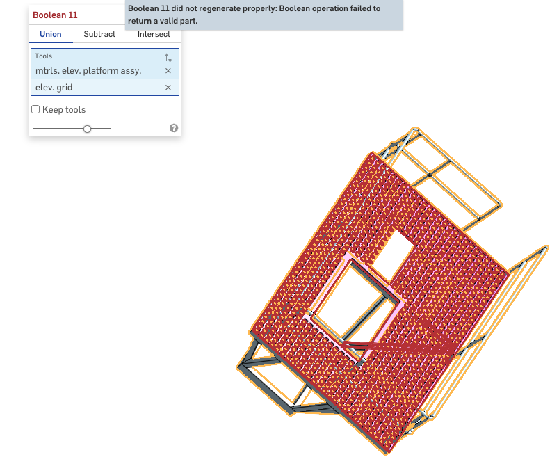
Why wont this Boolean?
 colin_king506
Member Posts: 64 ✭✭
colin_king506
Member Posts: 64 ✭✭
Best Answers
-
 Derek_Van_Allen_BD
Member Posts: 989 PRO
Derek_Van_Allen_BD
Member Posts: 989 PRO
779 features is now the highest I've seen in one single part studio tab. That's impressive that the build time is "only" ~20 seconds for the amount of geometric torture happening in there. Usually you see this kind of failure when there's some kind of zero thickness geometry, self intersecting parts, or volumes meeting at only a single edge instead of some true overlapping or butting region. I wouldn't be surprised in this case if the boolean feature just took one look at the truckload of face intersections impending and did one of these though:

But the bigger issue is for sure the document structure, that's gotta be painful to work in there at this point with that many features in one place. I would recommend referencing the Master Model Workflows article by Onshape and watching this video walkthrough I gave the other day of some of the modeling approach involved in the master part method to speed things up and get model stability
1 -
 glen_dewsbury
Member Posts: 1,349 PRO
glen_dewsbury
Member Posts: 1,349 PRO
I got your boolean to work, but I'm not sure why you'd want to. Gives boolean of boolean etc., amongst of things. There seams to be features given the same name as parts maybe causing incorrect selection between features and parts for the boolean. I made sure any other stuff like curves ere hidden the window selected the 2 remaining parts for the new boolean.
Any reason not to scale the imported image so that parts will be to scale when traced?
And what Derek said.
0
Answers
https://cad.onshape.com/documents/35f6d37e18282d4a33e380cb/w/dbcabc99944458f4e03125d2/e/84a09daa0bb7b8da44d9ae5f
It's a mess! I know!
779 features is now the highest I've seen in one single part studio tab. That's impressive that the build time is "only" ~20 seconds for the amount of geometric torture happening in there. Usually you see this kind of failure when there's some kind of zero thickness geometry, self intersecting parts, or volumes meeting at only a single edge instead of some true overlapping or butting region. I wouldn't be surprised in this case if the boolean feature just took one look at the truckload of face intersections impending and did one of these though:
But the bigger issue is for sure the document structure, that's gotta be painful to work in there at this point with that many features in one place. I would recommend referencing the Master Model Workflows article by Onshape and watching this video walkthrough I gave the other day of some of the modeling approach involved in the master part method to speed things up and get model stability
Derek Van Allen | Engineering Consultant | MeddlerI got your boolean to work, but I'm not sure why you'd want to. Gives boolean of boolean etc., amongst of things. There seams to be features given the same name as parts maybe causing incorrect selection between features and parts for the boolean. I made sure any other stuff like curves ere hidden the window selected the 2 remaining parts for the new boolean.
Any reason not to scale the imported image so that parts will be to scale when traced?
https://cad.onshape.com/documents/ad7ef6b83a1862b3824eaabe/w/1357451a45838ff836cd0ca9/e/5058c88b636a02e0fa480da3
And what Derek said.
@colin_king506 You've obviously put in a lot a work there. …And the recommendations above are valid, but maybe don't help you at this point.
I'll ask the question for you;
To the Onshape experts here. How would one even begin to break this up into multiple part studios? Said another way… if someone gave you this doc and said "fix it", just bill me the hours. How would you approach that?
-S
There's the careful approach and the aggressive approach, and I almost always default to the aggressive approach. In the past I would have conceptualized chunks of related geometry to carve out of the part studio and then duplicated the tab into that many chunks, then in each of the new studios start deleting features irrelevant to any of the smaller geometric assemblies to try to focus in on whatever matters to just that subset of geometry. In practice the issue with this approach is the modeling architecture is usually not clean to commit surgery on and you end up with less than ideal build time and waste a lot of potential progress hours fighting with features that break when you chop their legs out from under them, so the faster approach is to pull up a second monitor and draw the chunks from scratch and perform a full refactor with good architecture. It always sounds like the longer way around and it never ends up being that way because a clean document is so much faster to work on and you've already got a good reference for the target final product so it doesn't take as much time as you'd expect. Even starting "from zero"
Derek Van Allen | Engineering Consultant | MeddlerSo… to see if I can understand. You would sketch the solid of the .026 x .026 x .017 cube and then pattern it in the X and Y and… then remove them from the solid shape that is .017 thick? You obviously have WAY more 3D time than me.
An alternative way - probably more steps than you though:
Does this sound like a sound sequence?
I did it the Alternative way and I had no problem with the Boolean operation.
I may see my prior problem…
@Derek_Van_Allen_BD Other than starting over. Your approach sounds right to me.
And… "Show Dependencies.." is your friend. Learn how to use it.
to be fair I havn't looked at the model but usually with a question like that you start with f u pricing, then if accepted start from scratch. LOL