Welcome to the Onshape forum! Ask questions and join in the discussions about everything Onshape.
First time visiting? Here are some places to start:- Looking for a certain topic? Check out the categories filter or use Search (upper right).
- Need support? Ask a question to our Community Support category.
- Please submit support tickets for bugs but you can request improvements in the Product Feedback category.
- Be respectful, on topic and if you see a problem, Flag it.
If you would like to contact our Community Manager personally, feel free to send a private message or an email.
Flattening Airfoil Rib/Sheet Metal conversion
 tim_sundine
Member Posts: 6 ✭
tim_sundine
Member Posts: 6 ✭
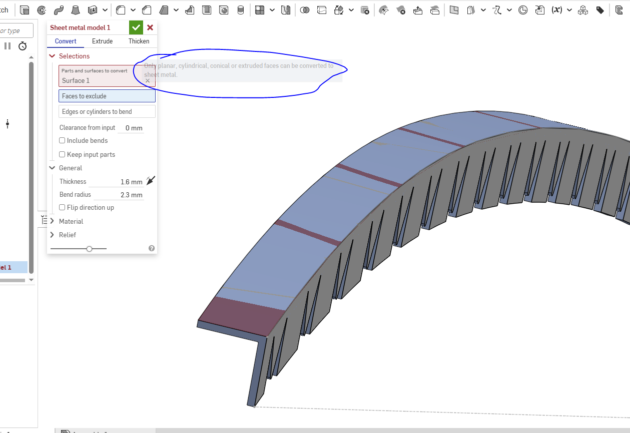
I have an airfoil section/rib that i want to flatten and be turned into a sheet metal part. it's split into two sections, there is on 90 bend, an L shape. Happy to convert to a face/surface but convert to sheet metal model throws the error, having a hard time finding applicable examples.
https://cad.onshape.com/documents/7448acf92361cdbe012a962e/w/b62d37e9071a776c1323eb1e/e/2326e3d972ba89c93a806bcf
Best Answers
-
 martin_kopplow
Member Posts: 1,450 PRO
martin_kopplow
Member Posts: 1,450 PRO
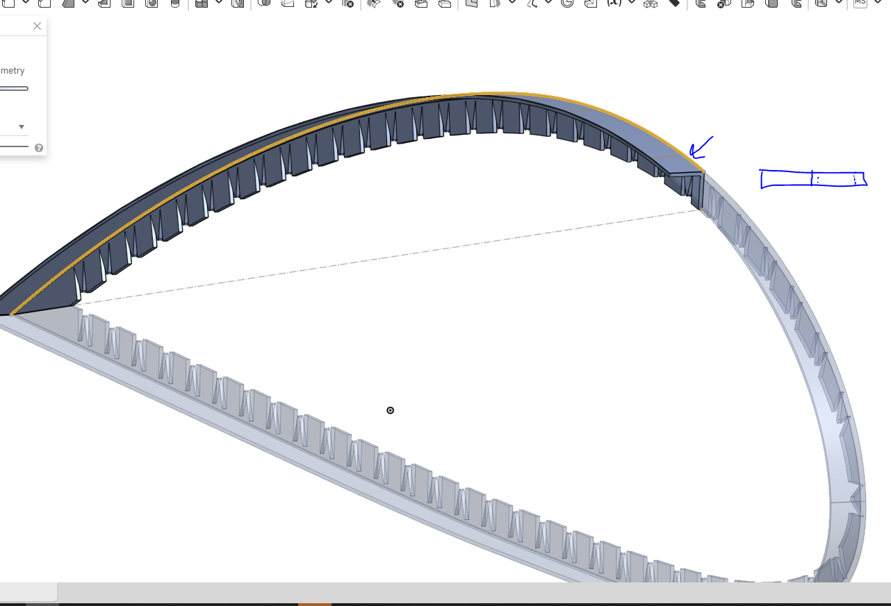
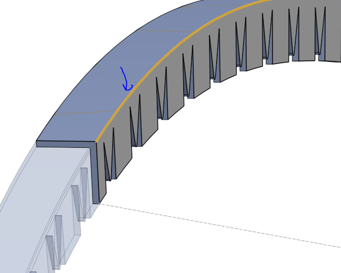
I'm afraid there's an issue with the way bend reliefs work. They would usually require your airfoil shape to be segmented and all the "teeth" be flanges that also have the 90° bend on their side.
What you got here is more or less an L-shape profile with cuts, then bent, rather than a flat sheet part folded and bent.
 1
1 -
 eric_pesty
Member, pcbaevp Posts: 2,761 PRO
eric_pesty
Member, pcbaevp Posts: 2,761 PRO
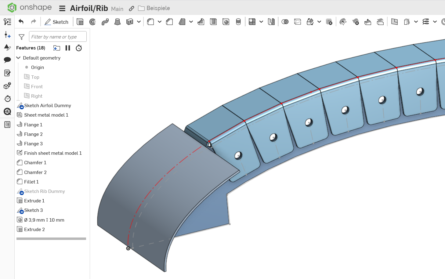
Have you tried using the sheet metal loft option? It should be able to go between the curves and break it up in flat faces with some tolerance…
Although it might only allow triangular faces?
EDIT: looks like it works if the profiles are identical (if not it creates triangles):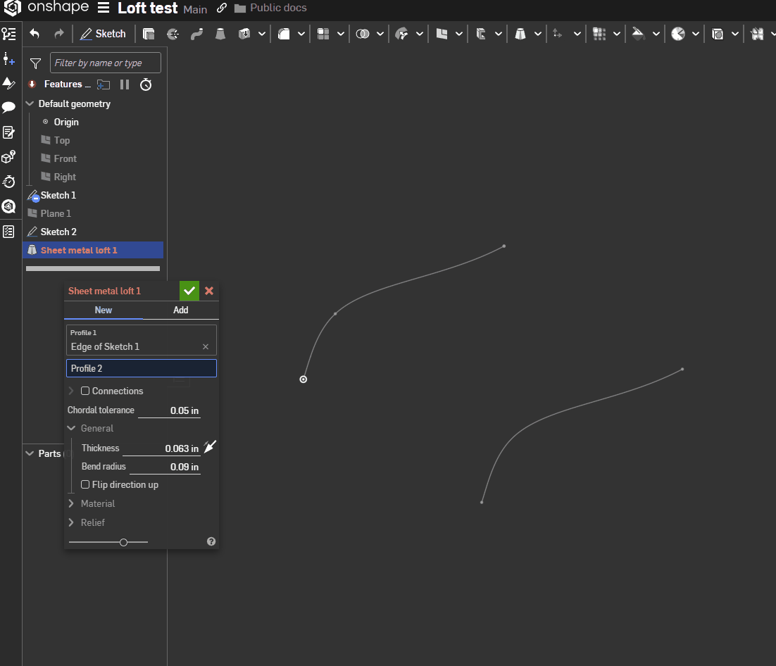 2
2
Answers
I'm afraid there's an issue with the way bend reliefs work. They would usually require your airfoil shape to be segmented and all the "teeth" be flanges that also have the 90° bend on their side.
What you got here is more or less an L-shape profile with cuts, then bent, rather than a flat sheet part folded and bent.
Thanks for the input, I'll explore this concept and the helpful model above.
So perhaps take a projection of the profile and split into equal distance flat sections/points vs the continuous spline. Is this primarily a geometric constraint within modeling/cad or in true mfg the tension on the top surface will require reliefs along the top just as much vs the continuous curve? I was thinking that the compression on the inside curve with the flange teeth. Sketch pattern along a curve or stuck with feature pattern along the curve? best to define the entire teeth profile in a single sketch for the entire airfoil rib curve?
Appreciate the helpful example and tip. I'll explore this more.
do the sections need to be modelled as linear flat sections between points along the profile, with a top surface relief at each section- or can be a thin sheet with the flanges and lines to model the relief curves for sheet model to convert into sections?
Thought process was that the compression side needs relief but the top surface in tension may not need it, except if that's not how it works for real world design/mfg then I can adjust that thinking.
Have you tried using the sheet metal loft option? It should be able to go between the curves and break it up in flat faces with some tolerance…
Although it might only allow triangular faces?
EDIT: looks like it works if the profiles are identical (if not it creates triangles):
I will look at the sheet metal loft option as well. thanks for the tip!