Welcome to the Onshape forum! Ask questions and join in the discussions about everything Onshape.
First time visiting? Here are some places to start:- Looking for a certain topic? Check out the categories filter or use Search (upper right).
- Need support? Ask a question to our Community Support category.
- Please submit support tickets for bugs but you can request improvements in the Product Feedback category.
- Be respectful, on topic and if you see a problem, Flag it.
If you would like to contact our Community Manager personally, feel free to send a private message or an email.
Parts in my assembly have skewed axes of movement using planar mates.
 eric_fisher438
Member Posts: 11 ✭
eric_fisher438
Member Posts: 11 ✭
Thank you to anyone who is reading this question. I have designed a speaker cabinet that will be built using plywood, and need to layout the parts flat to make toolpaths for CNC. I have used the Auto Layout feature script for other projects, but for this project I need to manually lay out and arrange the parts on a flat surface.
I created an assembly that contains a rectangle with the dimensions of a sheet of plywood. On that surface I am placing the various parts of the speaker cabinet using planar mates. Some of the parts mate as expected, allowing movement only on the X and Y axes, which are both parallel to the surface of the sheet, and rotate around Z. However, other parts have skewed X, Y and Z axes after mating, and I can not move them in the same way. Screenshots below.
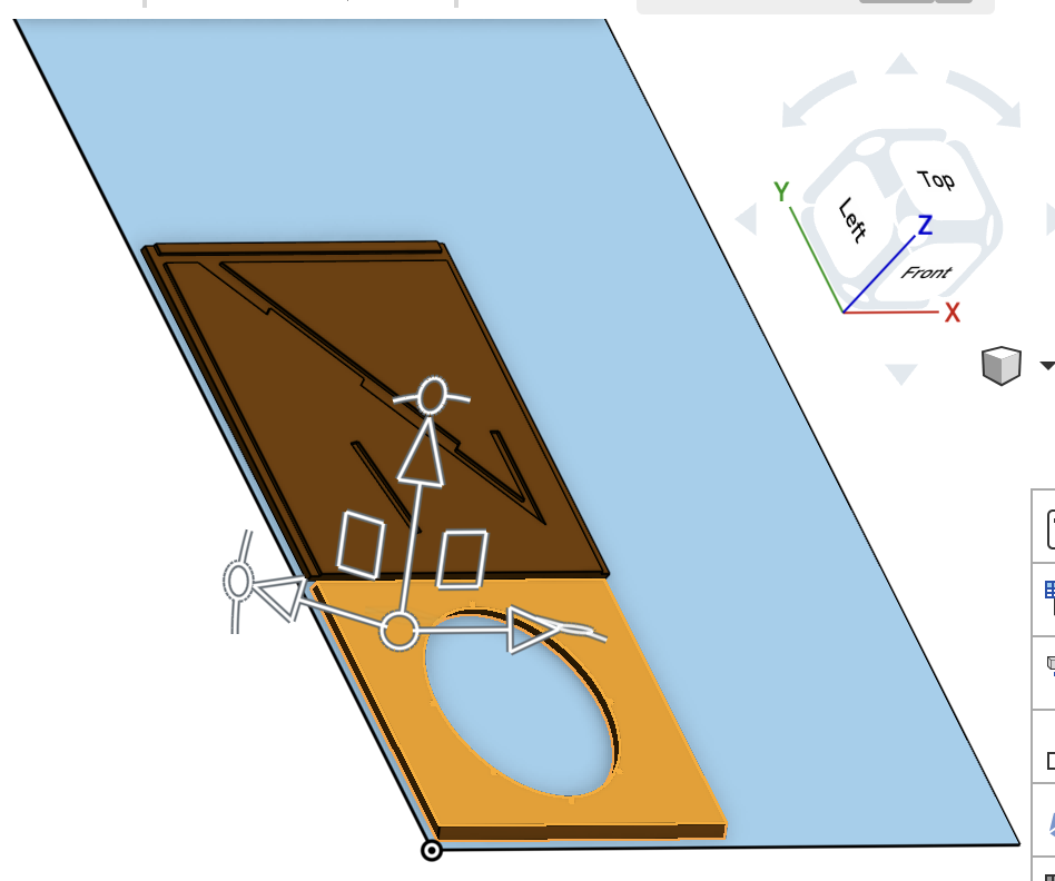
X and Y axes parallel to surface of blue part:
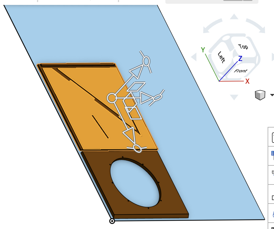
X and Y axes skewed in relation to the blue part:
Can anyone explain why the axes are skewed on some of the parts? Any other advice on how to mate the parts to the surface of the blue part allowing me to arrange them while keeping everything flat and parallel? Thanks for the help!
Link to document:
https://cad.onshape.com/documents/ae622757f483f2f31a0dcc01/w/3fb0240ad296a16db105d28f/e/8e82ee7edc7241fd3b8c3c22?renderMode=0&uiState=69dbfc020be6c12a8b5f7f1f
Edited to remove hyperlink.
Best Answer
-
 eric_pesty
Member, pcbaevp Posts: 2,758 PRO
eric_pesty
Member, pcbaevp Posts: 2,758 PRO
The triad will line up with the part axes by default, but you can drag the center to snap it to any implicit mate connector location and will re-orient itself to match what you dragged it to:
 1
1
Answers
The link is not working, sometimes the forum likes it pasted as plain text instead of a hyperlink.
From your screenshot, it must be the implicit mate connector (MC) that was picked for the parallel mate is not in the standard xyz direction. Always pick the part first, then the plywood second. The MC orientation of the part determines how it moves.
Thank you for the reply, I removed the hyperlink to the document and pasted it as plain text.
With regards to the mate connectors, I always select the face on the part first, then the plywood sheet second. The orientation of the part in question (in the original part studio) is approx 45 deg skewed from X and Y. If the MC orientation on the part determines how it moves, is there a way to re-orient the part so it only moves on X and Y parallel to the sheet of plywood? Would a different mate connector or method of placing the parts on the sheet work better? Thanks again.
The triad will line up with the part axes by default, but you can drag the center to snap it to any implicit mate connector location and will re-orient itself to match what you dragged it to:
I opened the document and it looks like everything moves ok. Did you figure it out?
Nice job overall! Browsing through the document there are a couple of unrelated things I saw that would help simplify things for the next project.
For off-the-shelf part imports, click the "create composite" option on the import. It makes the whole speaker 1 part, rather than the 16 parts it was that then require an assembly. This techicque is great for PCB's, ball bearings, power supplies, etc. You don't need the internal details of the speaker as separate parts, for example (or a ball bearing, or a pcb etc),. You just need to know its overall size and mounting provisions.
On your asm, nothing is mated (red box showing all parts can move). Instead, when you insert the parts, pick the blue boxes. The upper right one is called "rigid" and that means it inserts the entire part studio with all the parts locked together in their correct locations. Mates or groups aren't needed, and if you later add a part to the part studio, it will automatically show up in the correct place in the asm.
It would help a lot if the main shape was drawn centered on the origin. This helps because of symmetry. The sides could have been mirrored, including their dado cuts, with the click of one button. Same with all the internal ribs. That would save a lot of time and effort, in general.
Thanks for the reply. I did not know that you could drag the origin of the triad and snap it to a new location, this is very helpful!
As you can see I am still very much a novice at OnShape, thank you for taking the time to share these tips with me and post some screen caps. This is all very helpful! I learned a lot on this project, and would do many things differently next time. I can't thank you enough for making the effort to help out those of us who are learning. Cheers!