Welcome to the Onshape forum! Ask questions and join in the discussions about everything Onshape.
First time visiting? Here are some places to start:- Looking for a certain topic? Check out the categories filter or use Search (upper right).
- Need support? Ask a question to our Community Support category.
- Please submit support tickets for bugs but you can request improvements in the Product Feedback category.
- Be respectful, on topic and if you see a problem, Flag it.
If you would like to contact our Community Manager personally, feel free to send a private message or an email.
Show & Tell - Features from a mechanical designers point of view

traveler_hauptman
Member, OS Professional, Mentor, Developers Posts: 419 PRO
I finally got a window of time to take a look at FeatureScript and revisit Onshape after 9 months of working too hard.
Eventually I'd like to automate a bunch of aspects of my day-to-day mechanism design work. I have a couple projects I'd like to do with FS, but to get up to speed I decided to do a hole wizard, but from the perspective of a designer rather than a draftsman.
So my specification goes something like this:
So my hole wizard should take as inputs the two parts to compress, the materials, and any cosmetic requirements I have. That's it.
Optimization of screw thread, thread depth, web thickness, and screw distribution across a generic surface is a little ambitious for a 2 day project so I'll let that be an input for now.
So, the feature takes:
I started with a pair of solids complicated enough to be interesting and capture a reasonable amount of the design space.

Holes are defined by sketch point locations. Restrictions unrelated to the task at hand are a pet peeve of mine so there can be any number of points on any number of planes in any orientation. Each point, together with the plane it is drawn on, defines a hole axis.

Hole geometry is defined by the parts that have the holes in it so it does not matter where the planes are relative to the parts.
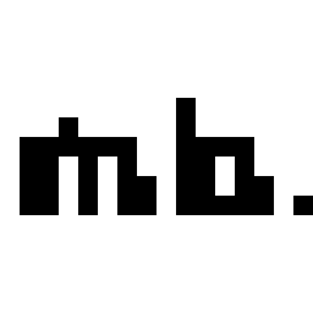
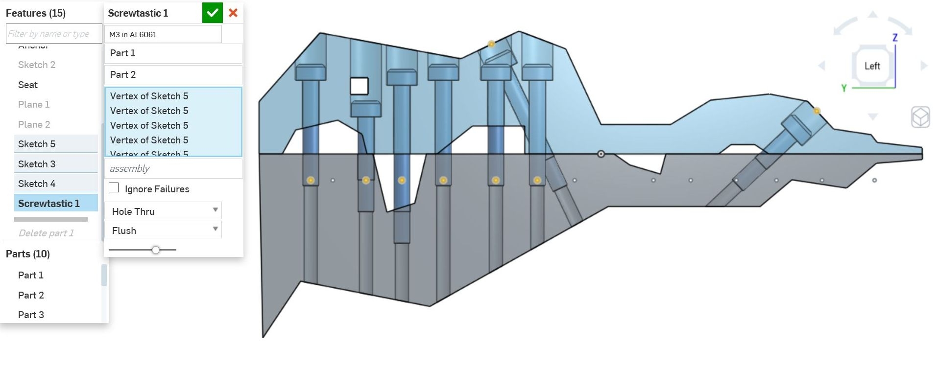
Then you select the two parts of the join, and the locations for your screws. In the following image one point caused an illegal condition (on the far right highlighted in debug orange) which if you hover for the error will tell you that there is not enough material for the required 6mm of thread engagement.
Finally you can give it info on whether to force the use of blind holes and how to choose the screw length.
That's it. The feature

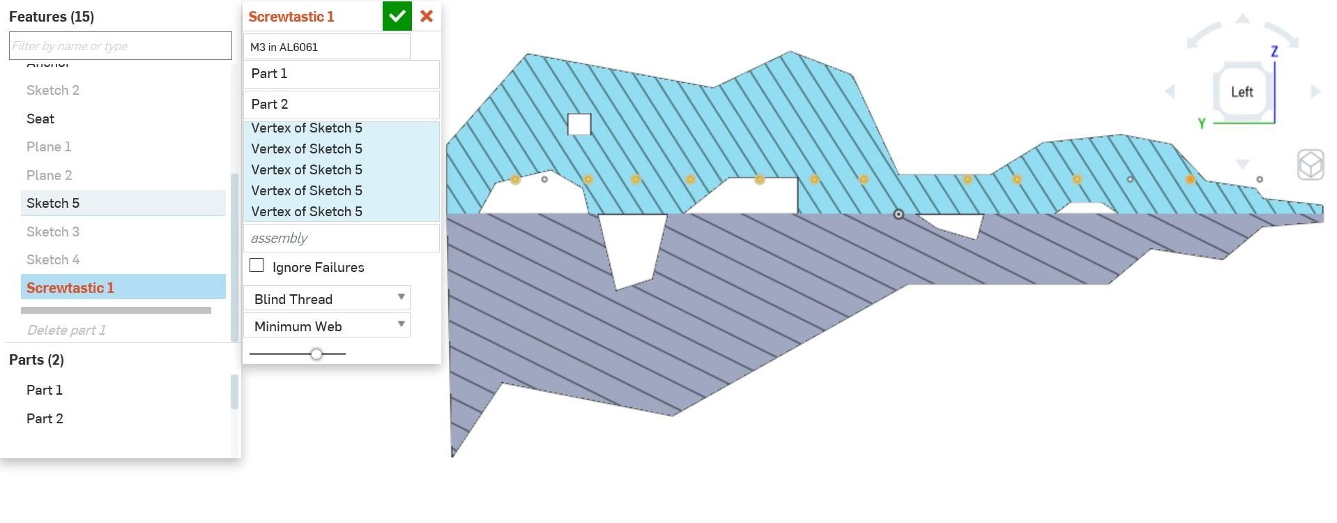
A different goal for the screw length that the designer might want is to minimize the counterbore. (It says flush, but that's mislabeled from another unimplemented mode that increases the thread engagement as needed to make the heads truly flush). Not shown here is the fact that the minimum web thickness is the dominant requirement, so the head will stick up above the surface if necessary to maintain that.
If there is not enough material in either part, it tells you and fails the rebuild. A full implementation of this feature would add threaded inserts and load distribution washers as necessary.
If minimizing part count is important, it will find a screw length from the available lengths that will fit all the material conditions. Notice I had to de-select some of the right side holes to find a solution. The errors guide you in this.

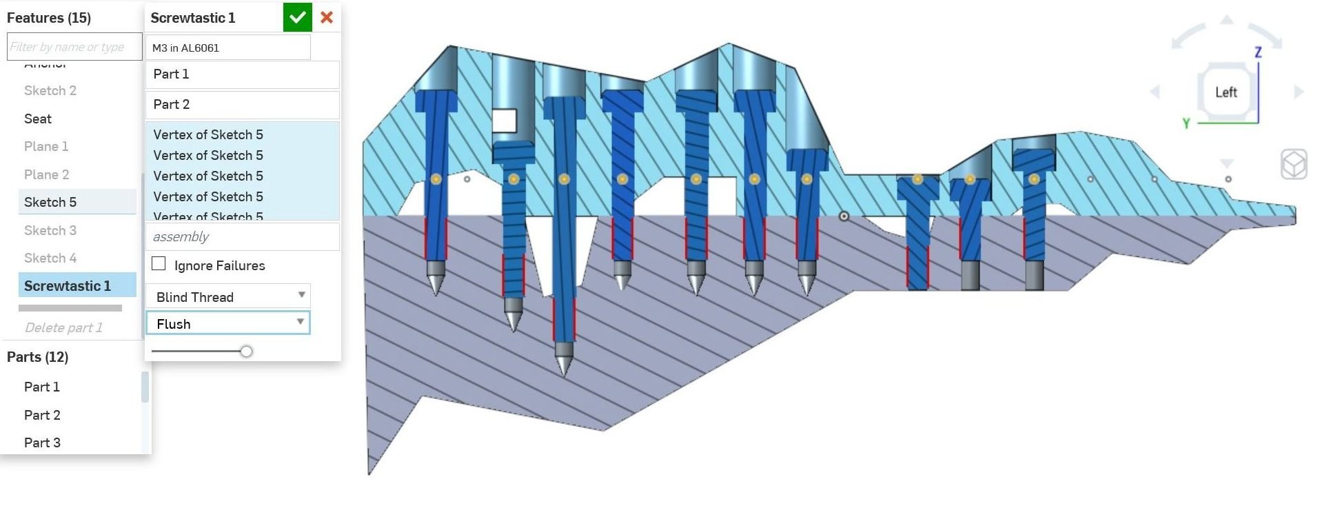
Sometimes thru holes are preferred for manufacturing purposes. No problem.

Again, the position of the features along the hole axis is defined by the parts we are seating in, not the location of the specification point. In the following I made no other change than flip the location of the points sketch plane. It rebuilds the same. As it should.

Here I swapped the two joint part selections.
As I mentioned before, the axis direction is taken from the plane the point is in. I added two points above the centerline, resting on the respective angled surfaces. Will it build !?!?

Yes of course. (The angled screws lie in a different plane and don't intersect the vertical ones). 'Same length' is selected so you can see it allowed the right angled screw to pop up out of the counterbore to do this (thread engagement is constrained to not change). BTW: The tap holes have a spotface added for manufacturing if the surface is not normal to the screw axis. The whole feature is restricted to subtractive processes. It won't add a boss under the head for instance.

Swapping the joint parts again.... I think the allowed screw lengths in this range are 20,25,30mm so it's having a hard time finding a length that fits nicely on the right.

With the equal length constraint relaxed, it selects shorter screws for the right side.
Return to blind holes and minimum web thicknesses.

I found it hard to grasp the data model until I read a parasolids document detailing the topology terminology. I'm not sure I took the best approach in analysing the geometry for the heuristics. I'm making heavy use of temporary solid tools and booleans.
I'll release the code for comment as soon as I clean up the unintelligible bits from the final couple hours.
I had performance problems while developing, but they are server issues rather that feature building issues. Rebuild from unsurpress when the server is behaving is about 2 seconds for the above model.
I'm still trying to understand the best way to import/export data. Dumping featurescript compatible maps from my other tools (Python and Lua mostly) seems like the way to go. Like others, I wish the import could follow workspaces as well as versions so that simultaneous development of library and working documents is not so painful to keep synced.
The code is about 800 lines with lots of cut and paste that could be compressed with functions. Two conditions which would need additional heuristics are large voids in the middle of a part, and having both sides of the joint be the same part (like a shaft clamp).
That's it for the show & tell. I'll document the heuristics if I can get the time. In case I don't....
This shows the tools used to understand the extents of the material each screw thread and screw head will be embedded in.
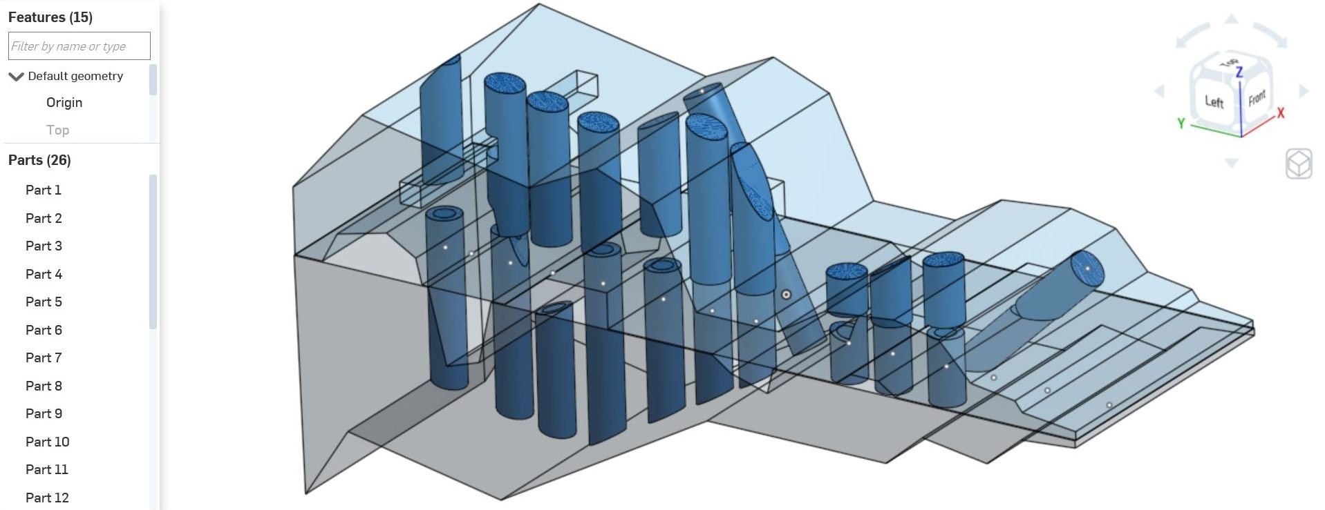
This shows the tools used to verify that the final thread location and final web (head) locations have the required material and that's it is unbroken (I compare the volumes of what's expected with what I measure.

Most of the heuristics are implemented by sampling the world using boolean intersection with tools of relevant shapes. However I also do some goofy face clustering in there too. The funky part shapes exposed lots of insufficient approaches as well. Had I used flat, constant thickness parts I would have ended up with something much less robust and not learned as much either.
Eventually I'd like to automate a bunch of aspects of my day-to-day mechanism design work. I have a couple projects I'd like to do with FS, but to get up to speed I decided to do a hole wizard, but from the perspective of a designer rather than a draftsman.
So my specification goes something like this:
- A screw joint holds two pieces together, preferably under compression.
- The compression load is dictated by the design requirements.
- The screw thread, depth, and support web follow from the compression load and choice of materials.
So my hole wizard should take as inputs the two parts to compress, the materials, and any cosmetic requirements I have. That's it.
Optimization of screw thread, thread depth, web thickness, and screw distribution across a generic surface is a little ambitious for a 2 day project so I'll let that be an input for now.
So, the feature takes:
- 2 parts,
- N sketch vertices (hole axis inferred from vertex plane normal),
- thread to use, (specs pulled from standards)
- thread engagement length & support web thickness, (specs chosen by designer or optimization)
- whether to prefer blind holes,
- how to choose screw length.
I started with a pair of solids complicated enough to be interesting and capture a reasonable amount of the design space.
Holes are defined by sketch point locations. Restrictions unrelated to the task at hand are a pet peeve of mine so there can be any number of points on any number of planes in any orientation. Each point, together with the plane it is drawn on, defines a hole axis.
Hole geometry is defined by the parts that have the holes in it so it does not matter where the planes are relative to the parts.

Then you select the two parts of the join, and the locations for your screws. In the following image one point caused an illegal condition (on the far right highlighted in debug orange) which if you hover for the error will tell you that there is not enough material for the required 6mm of thread engagement.
Finally you can give it info on whether to force the use of blind holes and how to choose the screw length.
That's it. The feature
- inspects the parts along each screw axis,
- verifies enough material for the requested thread engagement,
- punches blind holes through if they are close enough to cause dimpling on the back-side of the part,
- chooses the closest screw length from the list of standard lengths that will give as close to the target web thickness as possible,
- and (this is important) instantiates the screws. Why would I ever want a screw hole without a screw?
A different goal for the screw length that the designer might want is to minimize the counterbore. (It says flush, but that's mislabeled from another unimplemented mode that increases the thread engagement as needed to make the heads truly flush). Not shown here is the fact that the minimum web thickness is the dominant requirement, so the head will stick up above the surface if necessary to maintain that.
If there is not enough material in either part, it tells you and fails the rebuild. A full implementation of this feature would add threaded inserts and load distribution washers as necessary.
If minimizing part count is important, it will find a screw length from the available lengths that will fit all the material conditions. Notice I had to de-select some of the right side holes to find a solution. The errors guide you in this.
Sometimes thru holes are preferred for manufacturing purposes. No problem.
Again, the position of the features along the hole axis is defined by the parts we are seating in, not the location of the specification point. In the following I made no other change than flip the location of the points sketch plane. It rebuilds the same. As it should.
Here I swapped the two joint part selections.
As I mentioned before, the axis direction is taken from the plane the point is in. I added two points above the centerline, resting on the respective angled surfaces. Will it build !?!?
Yes of course. (The angled screws lie in a different plane and don't intersect the vertical ones). 'Same length' is selected so you can see it allowed the right angled screw to pop up out of the counterbore to do this (thread engagement is constrained to not change). BTW: The tap holes have a spotface added for manufacturing if the surface is not normal to the screw axis. The whole feature is restricted to subtractive processes. It won't add a boss under the head for instance.
Swapping the joint parts again.... I think the allowed screw lengths in this range are 20,25,30mm so it's having a hard time finding a length that fits nicely on the right.
With the equal length constraint relaxed, it selects shorter screws for the right side.
Return to blind holes and minimum web thicknesses.
I found it hard to grasp the data model until I read a parasolids document detailing the topology terminology. I'm not sure I took the best approach in analysing the geometry for the heuristics. I'm making heavy use of temporary solid tools and booleans.
I'll release the code for comment as soon as I clean up the unintelligible bits from the final couple hours.
I had performance problems while developing, but they are server issues rather that feature building issues. Rebuild from unsurpress when the server is behaving is about 2 seconds for the above model.
I'm still trying to understand the best way to import/export data. Dumping featurescript compatible maps from my other tools (Python and Lua mostly) seems like the way to go. Like others, I wish the import could follow workspaces as well as versions so that simultaneous development of library and working documents is not so painful to keep synced.
The code is about 800 lines with lots of cut and paste that could be compressed with functions. Two conditions which would need additional heuristics are large voids in the middle of a part, and having both sides of the joint be the same part (like a shaft clamp).
That's it for the show & tell. I'll document the heuristics if I can get the time. In case I don't....
This shows the tools used to understand the extents of the material each screw thread and screw head will be embedded in.
This shows the tools used to verify that the final thread location and final web (head) locations have the required material and that's it is unbroken (I compare the volumes of what's expected with what I measure.
Most of the heuristics are implemented by sampling the world using boolean intersection with tools of relevant shapes. However I also do some goofy face clustering in there too. The funky part shapes exposed lots of insufficient approaches as well. Had I used flat, constant thickness parts I would have ended up with something much less robust and not learned as much either.
1
Comments
-
Cool feature!
I'd like to understand the workflow issues a bit more: my imagined workflow is that you keep the "test" part studios in the same document so they are always synced to the latest committed features and when you want to actually "use" the feature, you version the document and put the feature in the toolbar. Were you wishing for a different workflow or was this one not working as expected (I know you had some intraworkspace sync issues -- was that what was in the way?)
For importing data to FS, you can also upload and import a CSV file. Print the BLOB_DATA constant the import brings in to see how to access the data. We're adding documentation for this...Ilya Baran \ VP, Architecture and FeatureScript \ Onshape Inc0 -
Yeah, my imagined workflow matches yours.ilya_baran said:Cool feature!
I'd like to understand the workflow issues a bit more: my imagined workflow is that you keep the "test" part studios in the same document so they are always synced to the latest committed features and when you want to actually "use" the feature, you version the document and put the feature in the toolbar. Were you wishing for a different workflow or was this one not working as expected (I know you had some intraworkspace sync issues -- was that what was in the way?)
For development I had the test instance of the feature and featurscript in the same document, each open in it's own tab so I can move between them easily. I have a featurescript library of common functions that is mostly static... I made 3 changes (and had to redo the import) during the course of a day.
There is some problem that causes long document-update/rebuild delays that I don't know the source of and have filed a ticket for. I don't think it's FS related.
I played with this after seeing some hints in a forum post. It took me a little head scratching to figure out that I needed multiple namespaces to import multiple blobs...I tried to access an uploaded *.FS file the same way and it did not work. Filtering by mime maybe? I didn't try a text file...
For importing data to FS, you can also upload and import a CSV file. Print the BLOB_DATA constant the import brings in to see how to access the data. We're adding documentation for this...
To be honest, my data is usually in something like YAML or LUA (or most easily dumped to that) rather than CSV. I'm forgetful and it's a lot easier to embed comments in those types of formats. If I need to do heavy lifting I use HDF5.
I really want to do:Bearings::import( path: "http://mechadept.com/data/bearing_data.fs");
....
var radius = Bearings::SKF.DGBB["606"].r;
For discoverability purposes, it might be better if you don't magically inject blob data into the global context. Forcing use of the namespace makes it really easy to learn.BLOB1::import(/*csv blob*/);
Not being able to inspect a namespace (eg println(BLOB1);) also makes it difficult.
var target = BLOB1::DATA.document_id;
0 -
Ok, I see. I can say that things like:
import( path: "http://mechadept.com/data/bearing_data.fs");
will not be possible because the data at the URL could go away (or just be slow) and a downstream user's feature would fail to regen (the big no-no in FeatureScript).Ilya Baran \ VP, Architecture and FeatureScript \ Onshape Inc0 -
@traveler_hauptman
Can you share a link to the FeatureScript?0