Welcome to the Onshape forum! Ask questions and join in the discussions about everything Onshape.
First time visiting? Here are some places to start:- Looking for a certain topic? Check out the categories filter or use Search (upper right).
- Need support? Ask a question to our Community Support category.
- Please submit support tickets for bugs but you can request improvements in the Product Feedback category.
- Be respectful, on topic and if you see a problem, Flag it.
If you would like to contact our Community Manager personally, feel free to send a private message or an email.
Library of sketch entities
 ml
Member Posts: 53 PRO
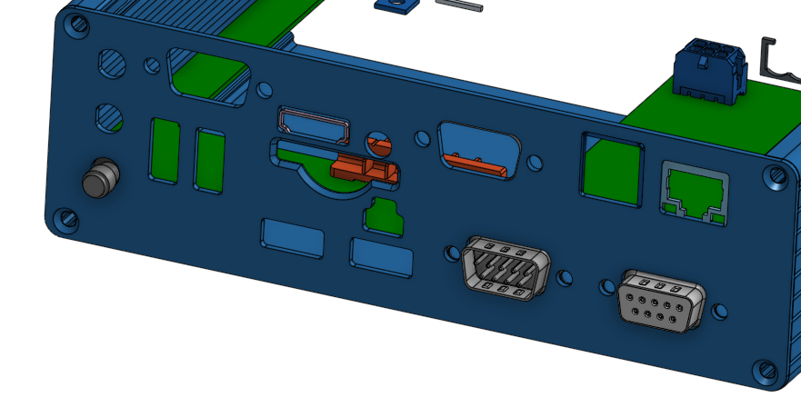
as mentioned in other threads, we use OS to design front and rear panels for electronic boards, means that we have to cut them for specific connectors.

while doing so, often standard components are used, for example d-sub connectors 9 pin on the bottom right.
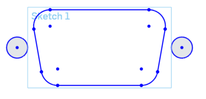
so we draw them in a sketch or import it from a dxf:

when we have them once, is there a way to bundle it in something like a library to easy insert it in the next document or is the only way 'copy entities' and 'paste entitites' which needs a document hopping?
btw: can the sketch rectangle and text in light blue be hidden like the planes?
best

while doing so, often standard components are used, for example d-sub connectors 9 pin on the bottom right.
so we draw them in a sketch or import it from a dxf:

when we have them once, is there a way to bundle it in something like a library to easy insert it in the next document or is the only way 'copy entities' and 'paste entitites' which needs a document hopping?
btw: can the sketch rectangle and text in light blue be hidden like the planes?
best
0
Answers
Check out the derived button's features. It will allow you to import a sketch from another document.
Developing this a bit, another option would be a featurescript function whereby you click a point on a sketch, select "9-Way D-Sub" from a drop down list and click OK.
This list could be expanded with different profiles, RJ11, RJ45 etc and we'd have a pretty slick tool for backplates. Hmm, I want one of those.
Cheers,
Owen S.
HWM-Water Ltd
I would like to help with this. I have built some routines that make it really easy for me to make a featurescript that generates sketches. If you can point me to a library of DXF files for all of these connectors, I can generate a FS that will let you create them all pretty quickly.
As an example, please reference this feature: its the same thing only instead of electronic parts, it is AISC steel sections. The AISC one i did has ability to create 1340 or so different drawings. The 8020 one can do about 1000 or so. So doing a bunch of standard electronic cutouts should be pretty do-able....
we do not have a full library of the connectores to import just now. there are in another program and we will only import them when they are become necessary. so, can we use your fs then when we need it? as a professional company, we have to had them under our control.
Because one can't insert into a sketch, only on part level, it does not match the need.
A featurescript as Dave suggests has got to be the best way to go here.
Just for the exercise of it I've had a play at a different method. Forgive the crude models they're just to show the theory.
(1) Build a library of "boolean solids" of the void to be removed. (The void required, not the actual connectors):-
(2) Make Back Plate with dimension of where to put features
(3) Add derived parts from the library and add mate connectors to the plate
(4) Transform Boolean Tools to mate connectors
(5) Boolean Subtract the tools.
It's a hash but would provide a parametric method to construct a plate from a library of parts...
Regards,
Owen S.
HWM-Water Ltd
Here the ideal solution is to be able to do step 2, and then in a single step, choose a profile and do step 5. I agree that's really only possible using a FS. Its simply too much trouble to import DXF--> make sketch--> import DXF --> extrude/subtract each time.
The FS profile option is so much cleaner for use in a thin plate.
I may have a play with the boolean option via FS. As it stands my crummy examples have a constant cross section so would give the same result as a profile but in a worse method. However if we have a thick plate the D-Type for example might need a counter-bore from the back to allow the connector to sit far enough forward to mate. In other circumstances anti-rotation features or assembly aid feature may be desirable. In these cases a boolean subtract from a 3D void tool may be desirable.
Just thinking out loud.
Owen S.
HWM-Water Ltd