Welcome to the Onshape forum! Ask questions and join in the discussions about everything Onshape.
First time visiting? Here are some places to start:- Looking for a certain topic? Check out the categories filter or use Search (upper right).
- Need support? Ask a question to our Community Support category.
- Please submit support tickets for bugs but you can request improvements in the Product Feedback category.
- Be respectful, on topic and if you see a problem, Flag it.
If you would like to contact our Community Manager personally, feel free to send a private message or an email.
Splitting a loft
 tcarrigan
Member Posts: 5 ✭
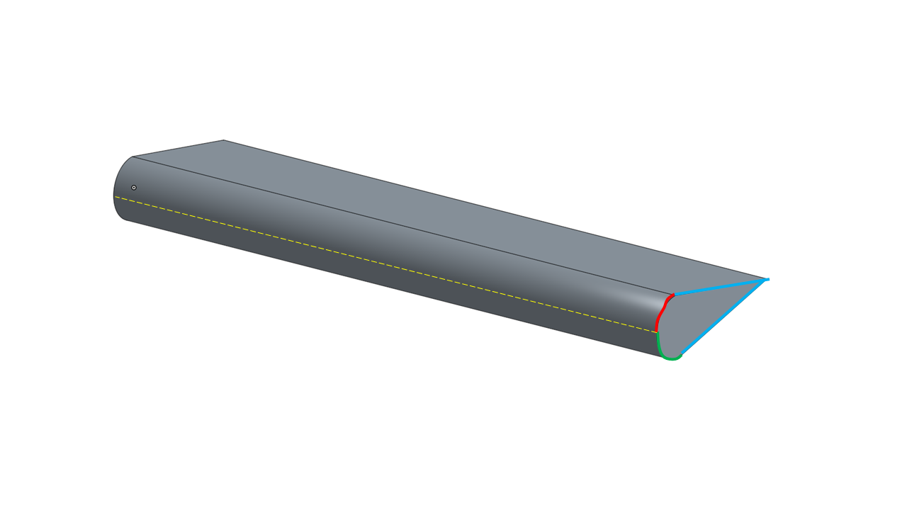
I have a simple wing like geometry that was created by performing a solid loft operation between two identical profiles, each consisting of four curves. As you can see, even though the profile consists of two curves (red and green) that represent the rounded leading edge, when performing the loft only a single surface is created for the leading edge. For my case, when performing a solid loft, I need the leading edge to be split along the dashed yellow line. I had wrongly assumed that there would be an edge running along the loft between the sets of vertices in each profile, but that is clearly not the case.
Rather than creating individual surface lofts for each profile curve, which is the only way I currently see this working, is there a way to get what I need? If not, I'll log a feature request to get this added.
Just a little background info for those interested. Being able to easily split along a leading edge like this that was created via the loft command, or similarly through the fillet operation, is essential for high-fidelity CFD (computational fluid dynamics) grid generation. The ability to use stretched elements can significantly reduce the overall cell count and computation time for a CFD simulation. However, leading edge curves are required to specify the correct boundary conditions for the grid generation algorithms that enable this type of meshing.

0
Answers
You can split any face with a plane or a surface using Split face.
With this example I split the face of the leading edges with a plane, but in this document I did it with a surface as well for more complex geometry. Hope this helps.
Jason
https://cad.onshape.com/documents/972dc31f395640d97dd6edca/w/8125816b48d1d07ebf0af701/e/31fa0727e4e6c9eb38ab1bb4
https://cad.onshape.com/documents/4bf18c75321ea2c8c2ea770d/v/a158158337c7f50415c36414/e/66a45520ab078f494b4346d1
Good luck!
I'm trying to split each wing element along the leading edge. This is probably more complex which is why I was looking for just a bit more guidance.
I think that in order to split the leading face you'd have to
- loft new individual surfaces of top or bottom curve,
- sweep the leading edges of these in some non-tangential direction,
- then split the faces of the solid with the swept surfaces...
Seems like you can't just loft the camber lines since the starting/ending angles differ even with the same end conditions, and you'd have to sweep because you can't extrude an edge apparently....which all in all is more work (on top of the solid lofting) than creating individual surface lofts for each profile curve anyways.
Wild guess: could it be that the edge is there, but Onshape just doesn't want to show it? Nothing shows up when you import it into whatever CFD software you're using?
I then tried to re-loft one of the elements as two separate halves, which seems to work, though this doesn't help you much either since OS currently lacks the ability to create "solids" out of surface bodies and vice-versa.
Yeah, it's a non-trivial process indeed...which it probably shouldn't be. I imported the geometry into my grid generation software and no, the edge is not there. The surfaces are rendered and accessible just as they are in Onshape.
What would be fantastic is if there were an option, just a checkbox, to create an edge between profile vertices when performing a solid loft.
projektowanieproduktow.wordpress.com